Photocatalysis and microorganism composite anode fuel battery system

A fuel cell system and composite anode technology, applied in biochemical fuel cells, fuel cells, battery electrodes, etc., can solve the problems of low output power density, difficult recycling of electrical energy, and high cathode cost, and achieve increased power density and cathode potential. Effect

Active Publication Date: 2015-03-04
HARBIN INST OF TECH
View PDF7 Cites 25 Cited by
  • Summary
  • Abstract
  • Description
  • Claims
  • Application Information

AI Technical Summary

Problems solved by technology

[0005] The purpose of the present invention is to solve the problems of low output power density, low generated voltage, difficult recycling of electric energy, high cathode cost and inability to continuously degrade biologically toxic organic substances in sewage in existing microbial fuel cells, and to provide a photocatalytic and microbial composite anode fuel cell system

Method used


Image

  • Photocatalysis and microorganism composite anode fuel battery system
  • Photocatalysis and microorganism composite anode fuel battery system
  • Photocatalysis and microorganism composite anode fuel battery system

Examples


specific Embodiment approach 1

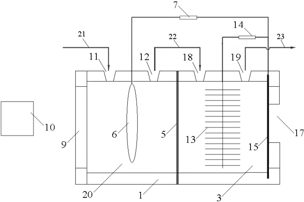
[0019] Specific Embodiment 1: This embodiment is a photocatalytic and microbial composite anode fuel cell system including a box body 1, a microbial anode chamber 3, an ion exchange membrane 5, a photocatalytic anode 6, a first resistor 7, a quartz glass window 9, Light source 10, photoanode chamber water inlet 11, photoanode chamber water outlet 12, microbial anode 13, second resistor 14, cathode 15, opening 17, microbial anode chamber water inlet 18, microbial fuel cell water outlet 19, photoanode chamber 20, water inlet pipe 21, conduit 22 and water outlet pipe 23;

[0020] One side of the box 1 is inlaid with a quartz glass window 9, the other side of the box 1 is provided with an opening 17, and the upper surface of the box 1 is provided with a photoanode chamber water inlet 11, a photoanode Chamber water outlet 12, microbial anode chamber water inlet 18 and microbial fuel cell water outlet 19; water inlet pipe 21 communicates with photoanode chamber water inlet 11, and p...

specific Embodiment approach 2

[0027] Specific embodiment two: the difference between this embodiment and specific embodiment one is: the photocatalytic anode 6 is a semiconductor material attached to the conductive substrate; the semiconductor material is titanium dioxide, ZnO, WO 3 or MoS 2 . Other steps are the same as in the first embodiment.

specific Embodiment approach 3

[0028] Specific embodiment three: the difference between this embodiment and specific embodiment one or two is that the microbial anode 13 is a microbial anode 13, and the microbial anode 13 is an electrochemically active biofilm attached to a carrier; the carrier is Carbon paper, carbon cloth, carbon fiber brush, carbon felt, glassy carbon, carbon nanotubes, graphite or graphene. Other steps are the same as those in Embodiment 1 or 2.


PUM

PropertyMeasurementUnit
electrical resistanceaaaaaaaaaa

Abstract

The invention provides a photocatalysis and microorganism composite anode fuel battery system, relates to a battery system and aims at solving the problems the output power density of the existing microbial fuel cell is low, the generated voltage is low, electricity energy is difficult to recycle, the cost of the negative electrode is high, and organic matters which have biotoxicity in sewage can not be continuously degraded. The photocatalysis and microorganism composite anode fuel battery system comprises a box body, a microorganism anode chamber, an ion exchange membrane, a photocatalysis anode, a resistor, a quartz glass window, a light source, a light anode chamber water inlet, a light anode chamber water outlet, a microorganism anode, a cathode, an opening, a microorganism anode chamber water inlet, a microorganism fuel battery water outlet, a light anode chamber, a water feeding pipe, a guide pipe and a water discharging pipe. According to the photocatalysis and microorganism composite anode fuel battery system, the luminous energy and the biological energy are utilized at the same time, and the production efficiency of the system is improved by 29-65%.

Description

technical field [0001] The invention relates to a battery system. Background technique [0002] Microbial fuel cell is a device that uses microorganisms as catalysts, uses industrial wastewater and domestic sewage as fuel, and directly converts chemical energy stored in biomass into electrical energy through the metabolism of microorganisms. new ideas. [0003] As an emerging energy and environmental protection technology, microbial fuel cells are still far from practical industrial applications. First, the output power density of microbial fuel cells is low, the generated voltage is low, and it is difficult to recycle electric energy. It is generally believed that the rate of the cathode reaction is the limiting factor for the performance of microbial fuel cells. Researchers have done a lot of work from the perspective of cathode materials and cathode catalysts in order to improve the performance of the cathode in microbial fuel cells, and then increase the power output ...

Claims


Application Information

Patent Timeline
Patent Type & Authority Applications(China)
IPC IPC(8): H01M4/86H01M4/92H01M8/16
CPCH01M8/0656H01M8/16Y02E60/50Y02P70/50
Inventor 冯玉杰杜月曲有鹏
Owner HARBIN INST OF TECH
Why Eureka
Try Eureka