Adjustable-delay optical buffer based on ring-shaped resonant cavity

A technology of ring resonator and optical buffer, which is applied in the field of optical communication, can solve the problems of high insertion loss and polarization dependence, high cost, and difficult connection between photonic crystal and single-mode optical fiber for communication, so as to reduce the cost of network construction, Flexible handling and solution to the effect of network congestion

Inactive Publication Date: 2015-03-04
NORTH CHINA UNIVERSITY OF TECHNOLOGY
View PDF4 Cites 9 Cited by
  • Summary
  • Abstract
  • Description
  • Claims
  • Application Information

AI Technical Summary

Problems solved by technology

[0004] For slowing down the speed of light, the most effective method is the electromagnetically induced transparency (EIT) technology based on the quantum coherence effect, but because it needs to be carried out at ultra-low temperature (close to absolute zero), the experimental system is too complicated and expensive
In addition, there are methods to slow down the speed of light by using high-dispersion two-dimensional waveguide photonic crystals, such as [Lu Peixiang, Yang Zhenyu, Chen Wei, etc., "An all-optical buffer ba

Method used


Image

  • Adjustable-delay optical buffer based on ring-shaped resonant cavity
  • Adjustable-delay optical buffer based on ring-shaped resonant cavity

Examples


Embodiment 1

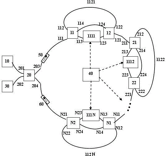
[0023] Embodiment one , figure 1 , an all-optical buffer with adjustable delay based on a ring resonator, comprising: an optical signal to be buffered 10, a zeroth 2×2 optical coupler 20, a first one to an Nth one 2×2 optical coupler 11, 21 , ..., N1, first, second to Nth second 2×2 optical couplers 12, 22, ..., N2, first to Nth optical phase modulators 1111, 1112, ..., 111N, first to first N single-mode optical fibers 1121, 1122, . . . , 112N, first and second optical isolators 50, 60, bit generator 40, and optical oscilloscope 30.

[0024] The connection of each device is as follows:

[0025] The signal 10 to be buffered is connected to the first port 201 of the zeroth 2×2 optical coupler, and the third port 203 of the zeroth 2×2 optical coupler is buffered with the first ring resonator via the first optical isolator 50 The input port of the unit is connected to form the input part of the optical signal;

[0026] The optical oscilloscope 30 is connected to the second po...

Embodiment 2

[0036] Embodiment two , figure 2 , an all-optical buffer with adjustable delay based on a single ring resonator, comprising: an optical signal to be buffered 10, a zeroth 2×2 optical coupler 20, a first-12×2 optical coupler 11, a first-two 2 ×2 optical coupler 12 , optical phase modulator 1111 , single-mode optical fiber 1121 , first optical isolator 50 , second optical isolator 60 , bit generator 40 , and optical oscilloscope 30 .

[0037] The connection of each device is as follows:

[0038] The signal to be buffered 10 is connected to the first port 201 of the zeroth 2×2 optical coupler, and the third port 203 of the zeroth 2×2 optical coupler is connected to the ring resonator buffer unit through the first optical isolator 50 The input port 111 is connected to form the input part of the optical signal;

[0039] The optical oscilloscope 30 is connected to the second port 202 of the zeroth 2×2 optical coupler, and the fourth port 204 of the zeroth 2×2 optical coupler is...


PUM


Abstract

The invention discloses an adjustable-delay optical buffer based on a ring-shaped resonant cavity, wherein the connection of each part is as follows: a first port of an optical coupler (20) is connected with a to-be-buffered optical signal (10), a third port of the optical coupler (20) is connected with buffer unit input (111) of a first ring-shaped resonant cavity buffer unit by an optical isolator (50) to form an optical signal input part; a second port of the optical coupler (20) is connected with an optical oscilloscope (30), a fourth port of the optical coupler (20) is connected with output of an optical isolator (60) to form an optical signal output part; output (121, 221, ..., N21) of the first to the N-th ring-shaped resonant cavity buffer units are respectively connected with input (211, 311, ..., N11) of the second to the N-th ring-shaped resonant cavity buffer units and the input of the second optical isolator (60) to form an optical signal buffer part; and a bit generator (40) is used for controlling a first to a N-th optical phase modulators (1111, 1112, ..., 111N) to form an optical signal delay regulating part.

Description

technical field [0001] The invention belongs to the technical field of optical communication, is suitable for storing, controlling and processing high-speed optical signals, and in particular relates to an all-optical buffer based on a ring resonant cavity with adjustable delay. Background technique [0002] The information network is composed of transmission and exchange. At present, the transmission part has completed the revolution from electricity to light. However, it obviously does not match the ultra-large-capacity optical transmission. The processing of information still uses electronic devices, which are limited by photoelectric conversion and electronic devices. The speed of data processing can easily cause congestion of the information network. In order to effectively improve the throughput of all-optical network nodes and avoid network competition among different users, an optical buffer device that can effectively delay or buffer optical signals is urgently need...

Claims


Application Information

Patent Timeline
IPC IPC(8): H04B10/25G02B6/28
Inventor 董小伟张强强
Owner NORTH CHINA UNIVERSITY OF TECHNOLOGY
Why Eureka
Try Eureka