Magnetic material composition and coil component

A coil component and magnetic body technology, applied in the direction of magnetic objects, magnetic materials, inorganic materials, etc., can solve the problems of difficult magnetic saturation, low insulation, high saturation magnetic flux density, etc., and achieve good plating solution resistance

Active Publication Date: 2015-03-04
MURATA MFG CO LTD
View PDF8 Cites 7 Cited by
  • Summary
  • Abstract
  • Description
  • Claims
  • Application Information

AI Technical Summary

Problems solved by technology

[0003] Compared with ferrite materials, this magnetic alloy material has a higher saturation magnetic flux density and is less likely to be magnetically saturated, but requires insulation treatment because of its low insulation

Method used


Image

  • Magnetic material composition and coil component
  • Magnetic material composition and coil component
  • Magnetic material composition and coil component

Examples


Embodiment 1

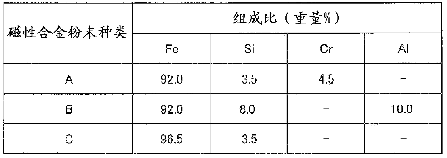
[0083] Commercially available Fe—Si—Cr-based magnetic alloy particles (magnetic alloy particles A), Fe—Si—Al-based magnetic alloy particles (magnetic alloy particles B) and Fe—Si-based magnetic alloy particles (magnetic alloy particles B) shown in Table 1 were prepared. Alloy particles C). It should be noted that the average particle diameters of these magnetic alloy particles A to C are all 6 μm.

[0084] Table 1 shows the respective composition ratios of the magnetic alloy particles A to C.

[0085] [Table 1]

[0086] [Table 1]

[0087]

[0088] In addition, prepare SiO 2 , B 2 o 3 、K2 Each glass raw material of O and ZnO was mixed so that it might become the composition shown in Table 2, and glass components a-f were produced. Then, the softening points of these glass components a to f were measured in accordance with JIS3103-1. In addition, the average particle diameters of the glass components were all 1 micrometer.

[0089] Table 2 shows the respective composi...

Embodiment 2

[0117] Magnetic pastes used in sample numbers 4, 7, 9, 12, and 19 of Example 1 were prepared.

[0118] In addition, an internal conductor paste containing Ag powder, lacquer, and organic solvent is prepared.

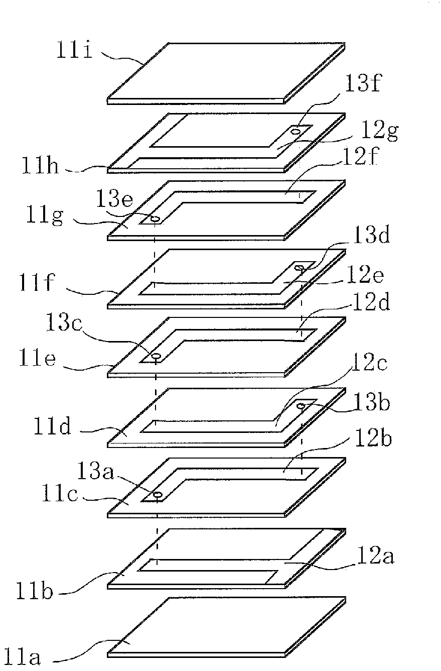
[0119] Next, the magnetic substance paste was applied and dried on the PET film, and this operation was repeated a predetermined number of times to produce a magnetic substance sheet. Next, the internal conductor paste was applied on the surface of the magnetic sheet by the screen printing method, and dried to form a conductor layer in a predetermined pattern.

[0120] Next, the magnetic substance paste was applied on the magnetic substance sheet on which the conductor layer was formed, and it dried, and the magnetic substance sheet was produced. At this time, through holes are formed at predetermined positions of the magnetic sheet. Next, the internal conductor paste was applied to the surface of the magnetic sheet by a screen printing method, and dried to form a cond...


PUM

PropertyMeasurementUnit
softening pointaaaaaaaaaa

Abstract

This magnetic material composition comprises: magnetic alloy particles of an Fe-Si-Cr system, an Fe-Si-Al system or the like, with the surface of each particle being provided with a passivation film; and a glass component that has a softening point of 650-800°C and contains Si, B and an alkali metal such as K, Na or Li. The content of the glass component relative to the total amount of the magnetic alloy particles and the glass component is 12-32 wt%, and a glass phase formed of the glass component is formed between the magnetic alloy particles. A component element (1), in which a coil conductor (2) is embedded, is formed from this magnetic material composition. Consequently, ingress of water or a plating liquid between the magnetic alloy particles can be suppressed, thereby ensuring good insulation without deteriorating the magnetic characteristics.

Description

technical field [0001] The present invention relates to a magnetic composition and a coil component. More specifically, it relates to a magnetic composition mainly composed of a magnetic alloy material, and various coil components using the magnetic composition. Background technique [0002] Conventionally, for coil components used in choke coils used at high frequencies, power supply circuits through which large currents flow, and power inductors for DC / DC converter circuits, magnetic alloy particles are widely used. A magnetic composition excellent in DC superposition characteristics. [0003] Such a magnetic alloy material has a higher saturation magnetic flux density and is less likely to be magnetically saturated than a ferrite material, but requires insulation treatment because of its low insulating properties. [0004] Therefore, for example, in Patent Document 1, a coil-type electronic component is proposed in which the substrate is composed of a particle group of a...

Claims


Application Information

Patent Timeline
Patent Type & Authority Applications(China)
IPC IPC(8): H01F1/24H01F1/147H01F17/00H01F17/04
CPCH01F17/0033H01F1/24Y10T428/2924H01F1/147H01F17/00H01F17/04H01F1/01H01F27/255
Inventor 前田英一高桥亨
Owner MURATA MFG CO LTD
Why Eureka
Try Eureka