Two-end pre-tightening type low-friction-characteristic cylinder with cylinder body in multi-mode vibration caused by piezoelectric stacks

A piezoelectric stack and multi-mode technology, applied in the direction of fluid pressure actuation devices, can solve the problems of difficult manufacturing, oil pollution, and low reliability, and achieve easy processing, strong applicability, and high reliability. Effect

Inactive Publication Date: 2015-03-11
HARBIN INST OF TECH
View PDF8 Cites 18 Cited by
  • Summary
  • Abstract
  • Description
  • Claims
  • Application Information

AI Technical Summary

Problems solved by technology

[0006] The purpose of the present invention is to provide a low-friction characteristic cylinder with multi-modal vibration of the cylinder body caused by the pre-tightened piezoelectric stack at both ends. Problems of large volume, oil pollution, low output and low reliability

Method used


Image

  • Two-end pre-tightening type low-friction-characteristic cylinder with cylinder body in multi-mode vibration caused by piezoelectric stacks
  • Two-end pre-tightening type low-friction-characteristic cylinder with cylinder body in multi-mode vibration caused by piezoelectric stacks

Examples


specific Embodiment approach 1

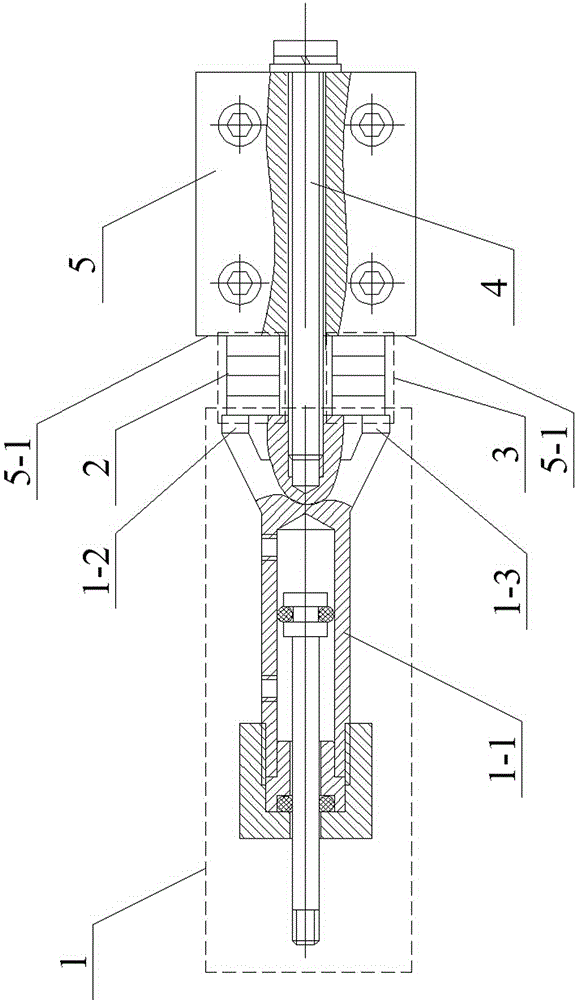
[0012] Specific implementation mode one: combine figure 1 Describe this embodiment. This embodiment is composed of a general-purpose cylinder assembly 1, a first piezoelectric stack 2, a second piezoelectric stack 3, fastening bolts 4, and a mounting seat 5;

[0013] The two sides of the tail end of the cylinder barrel 1-1 of the general-purpose cylinder assembly 1 are respectively provided with a first support foot 1-2 and a second support foot 1-3, and the bottom end surface of the first support foot 1-2 is connected with the first piezoelectric One end face of the stack 2 is top-connected, the bottom end face of the second support leg 1-3 is connected to one end face of the second piezoelectric stack 3, the other end face of the first piezoelectric stack 2, the other end face of the second piezoelectric stack 3 Both are top-connected with the end face 5-1 of the mounting seat 5, and the fastening bolt 4 passes through the mounting seat 5 and is threadedly connected with the...

specific Embodiment approach 2

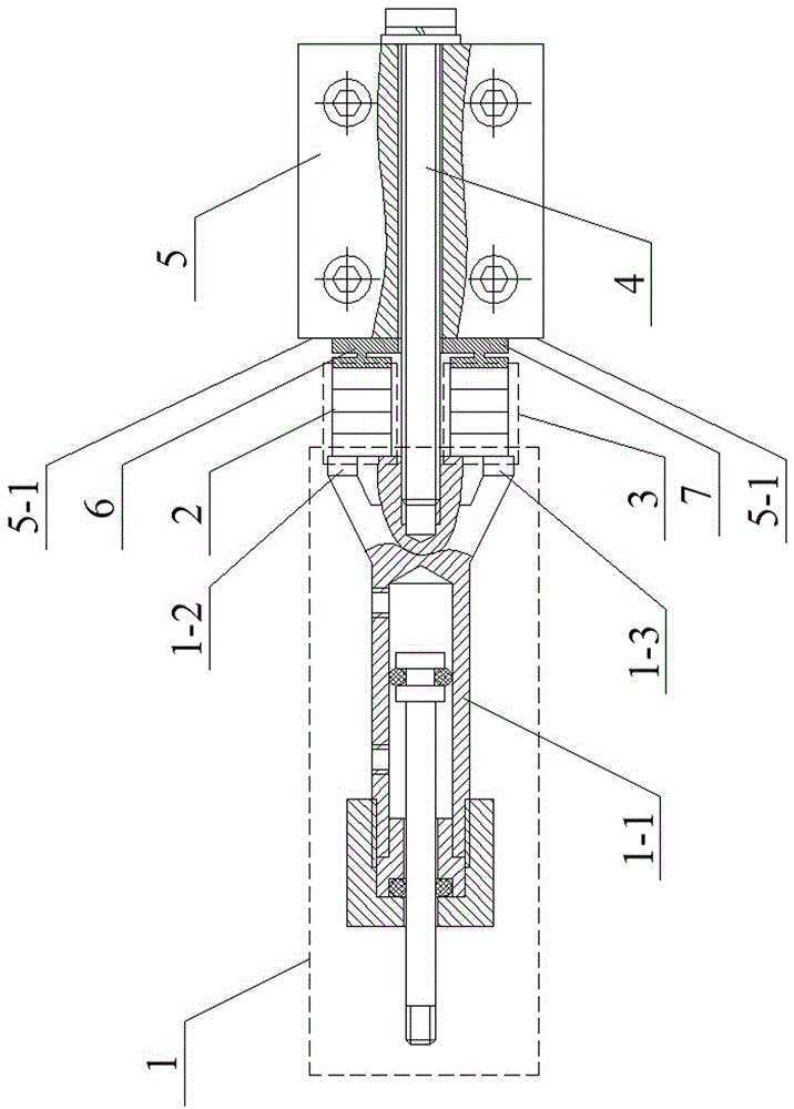
[0017] Specific implementation mode two: combination figure 2 Describe this embodiment, this embodiment adds a first H-shaped flexible hinge 6 and a second H-shaped flexible hinge 7 on the basis of the first specific embodiment; the first H-shaped flexible hinge 6 is arranged between the first piezoelectric stack 2 and the Between the end faces 5-1, the second H-shaped flexible hinge 7 is arranged between the second piezoelectric stack 3 and the end faces 5-1.

[0018] This embodiment has the functions of increasing the rotational freedom of the fastening bolt 4 in the axial direction, optimizing the vibration effect, and prolonging the working life of the first piezoelectric stack 2 and the second piezoelectric stack 3 .


PUM


Abstract

The invention discloses a two-end pre-tightening type low-friction-characteristic cylinder with a cylinder body in multi-mode vibration caused by piezoelectric stacks, relates to the technical field of pneumatic control, and aims at solving the problems that an existing friction reducing structure is large in noise, short in service life, high in manufacturing difficulty, large in size, prone to oil liquid pollution, low in output and low in reliability. A first supporting leg and a second supporting leg are arranged on two sides of the tail end of a cylinder barrel of a general cylinder assembly respectively; the bottom end surface of the first supporting leg is propped against one end surface of a first piezoelectric stack; the bottom end surface of the second supporting leg is propped against one end surface of a second piezoelectric stack; the other end surface of the first piezoelectric stack and the other end surface of the second piezoelectric stack are propped against the end surface of a mounting seat; a fastening bolt penetrates through the mounting seat and then is in threaded connection with the bottom of the tail end of the cylinder barrel, so that the axis of the fastening bolt coincides with that of the cylinder barrel of the general cylinder assembly. According to the cylinder, more than 50 percent of friction between a piston (a piston rod) and the cylinder body can be reduced under a supersonic vibration resonance state, and the friction reducing effect is good.

Description

technical field [0001] The invention relates to the technical field of pneumatic control. Background technique [0002] When the piston of the cylinder is working at a low speed, it often occurs a discontinuous movement phenomenon of running and stopping, that is, the cylinder crawls. Cylinder crawling seriously affects the accuracy of pneumatic transmission. In order to eliminate this phenomenon, the common method is to superimpose the dither signal on the control signal to compensate the friction of the cylinder. However, the introduction of the dither signal greatly reduces the life of the control valve and brings unnecessary noise and jitter, so the application is limited. [0003] Another method is to use the principle of air flotation to introduce a layer of air film between the friction pairs of the cylinder, thereby significantly reducing the dynamic and static friction of the cylinder, and greatly improving the crawling phenomenon of the cylinder. Such as patent ...

Claims


Application Information

Patent Timeline
Patent Type & Authority Applications(China)
IPC IPC(8): F15B15/14F15B15/20
CPCF15B15/1423F15B15/20
Inventor 高焓包钢程廷海
Owner HARBIN INST OF TECH
Why Eureka
Try Eureka