Variable-reluctance stimulation and decoding module for measuring position angle of rotor of permanent magnet synchronous motor

A technology of permanent magnet synchronous motor and rotor position angle, which is applied in the direction of measuring device, electric device, and electromagnetic means, etc. It can solve the problems that cannot be used in large quantities, the hardware decoding chip is expensive, etc., and achieve signal stability, cost saving, and anti-corrosion. Disturbing effect

Active Publication Date: 2015-03-11
HANGZHOU XIANGBIN ELECTRONICS TECH
View PDF6 Cites 16 Cited by
  • Summary
  • Abstract
  • Description
  • Claims
  • Application Information

AI Technical Summary

Problems solved by technology

[0005] The main purpose of the present invention is to provide a circuit module for measuring the rotor position angle of a permanent magnet synchronous motor. Position angle signal, so as to solve the problem that cannot be used in large quantities due to the high price of the hardware decoding chip

Method used


Image

  • Variable-reluctance stimulation and decoding module for measuring position angle of rotor of permanent magnet synchronous motor
  • Variable-reluctance stimulation and decoding module for measuring position angle of rotor of permanent magnet synchronous motor
  • Variable-reluctance stimulation and decoding module for measuring position angle of rotor of permanent magnet synchronous motor

Examples


Embodiment Construction

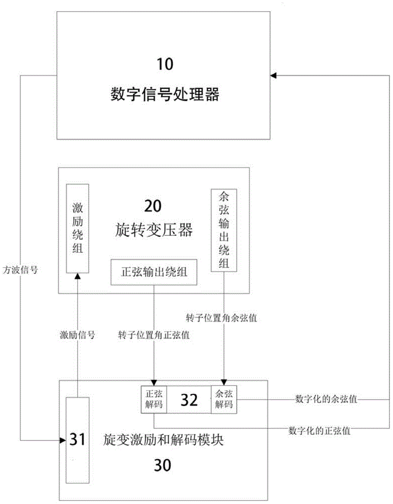
[0041] refer to figure 1 , the preferred embodiment of this module 30 is mainly composed of a signal excitation circuit 31 and a signal decoding circuit 32, the signal excitation circuit 31 obtains the square wave excitation signal of the digital signal processor 10, and is used to provide the rotary transformer 20 of the permanent magnet synchronous motor The excitation signal, the signal decoding circuit 32 is used to perform signal conversion on the rotor sine and cosine position angle signals of the sine output winding and cosine output winding of the rotary transformer 20 collected back, and finally output the digitized absolute position signal to the digital signal processor 10.

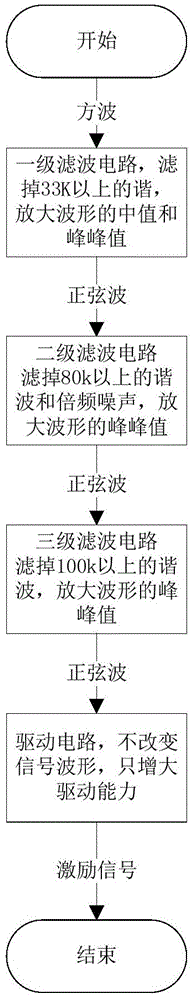
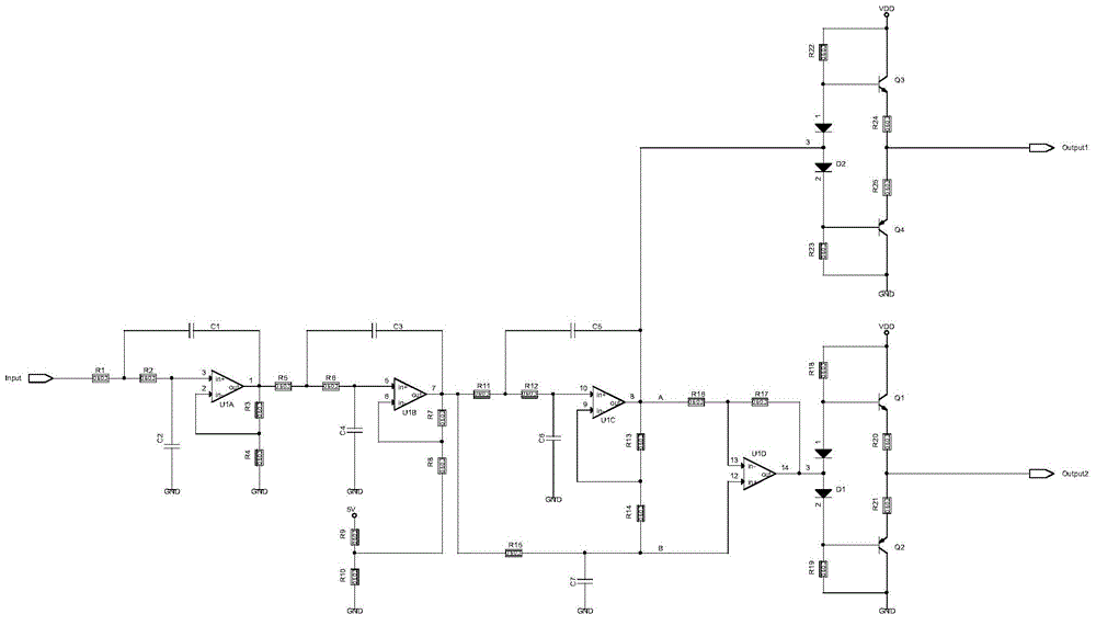
[0042] refer to figure 2 , the excitation circuit uses a three-stage filter amplification form, and finally outputs a signal that can drive the excitation winding of the resolver. In this example, the frequency of the square wave is required to be 10KHz, the median value of the output sine wav...


PUM


Abstract

The embodiment of the invention designs a variable-reluctance stimulation and decoding module for measuring position angle of a rotor of a permanent magnet synchronous motor. The variable-reluctance stimulation and decoding module comprises a signal stimulation circuit, a signal decoding circuit, wherein the signal stimulation circuit is used for converting a digital square signal of a signal processor into a sine wave stimulation signal for driving a rotating transformer and comprises a multi-stage filtering amplification circuit for generating a sine wave signal, a push-pull circuit connected with the output end of the multi-stage filtering amplification circuit, and a stimulation winding for improving the driving capability of the signal so as to drive the rotating transformer; the signal decoding circuit is used for decoding the output signal of the rotating transformer and comprises a differential amplification circuit, a rectification turning circuit and a filtering circuit; the differential amplification circuit is used for receiving a differential signal output by the rotary transformer and outputting an amplified echo signal; the rectification turning circuit is used for extracting an envelope line of an echo signal; the filtering circuit is used for filtering the turned echo signal into a flat level signal. According to the embodiment, the cost is effectively reduced, and the function of a decoding chip can be achieved by using only resistance-capacitance devices and operational amplifiers.

Description

technical field [0001] Embodiments of the present invention relate to the field of motor control, and more specifically, the present invention provides a circuit module for measuring the rotor position angle of a permanent magnet synchronous motor. Background technique [0002] For permanent magnet synchronous motors embedded with a resolver, the detection of the rotor position is determined by collecting the signal output from the resolver. The resolver has the advantages of high temperature resistance, humidity resistance, impact resistance, anti-interference and high precision. Widely used in automotive control systems. The resolver is an analog device that outputs an AC modulation signal. In a digital control system, it is often necessary to convert the output signal of the resolver into a digital angle signal. Common resolver angle decoding methods include the method of decoding with a hardware decoding chip and the method of decoding with software based on DSP. [00...

Claims


Application Information

Patent Timeline
Patent Type & Authority Applications(China)
IPC IPC(8): G01B7/30
Inventor 蔡斌景立群宋士伟
Owner HANGZHOU XIANGBIN ELECTRONICS TECH
Why Eureka
Try Eureka