Al technical title is built by PatSnap Al team. It summarizes the technical point description of the patent document.
A sampling device and particulate matter technology, applied in the field of sampling devices and condensable particulate matter sampling devices, can solve the problems of not representing a fixed source, negative effects, etc., and achieve the effects of reducing residual loss, fast cooling speed, and reducing blocking loss.
Active Publication Date: 2015-03-11
深圳睿境环保科技有限公司
View PDF8 Cites 13 Cited by
Summary
Abstract
Description
Claims
Application Information
AI Technical Summary
This helps you quickly interpret patents by identifying the three key elements:
Problems solved by technology
Method used
Benefits of technology
Problems solved by technology
Foreign studies have pointed out that for coal-fired boilers, in terms of mass, condensable particulate matter emissions account for the total PM 10 76% of PM emissions and 49% of total PM emissions, which means: first, my country’s current test results for stationary source particulate matter (that is, filter particulate matter) cannot represent the real emissions of stationary sources; second, condensable particulate matter belongs to fine particulate matter and in total PM 10 The share of emissions is very large, and the degree of enrichment gradually increases with the reduction of particle size. If it is not considered, it will definitely have a negative impact on the formulation of policies for the control of inhalable particulate matter in ambient air.
Method used
Image
Click on the blue label to locate the original text in one second.
Reading with bidirectional positioning of images and text.
Examples
Embodiment
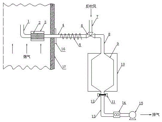
[0022] Such as Figure 1-3 The condensable particulate matter sampling device shown includes a sampling head 1, a filter 2, a heater 3, a sampling pipe 4, a heating cable 5, a three-way ball valve 6, a blowback pipe 7, an air inlet pipe 8, a condenser 9, and a refrigerator 10 , filter clip 11, filter membrane 12, exhaust pipe 13, flow meter 14, vacuum pump 15.
[0023] Sampling head 1, filter 2, sampling pipe 4, three-way ball valve 6, inlet pipe 8, condenser 9, filter membrane clamp 11, exhaust pipe 13, flow meter 14, and vacuum pump 15 are connected in sequence. The sampling head 1 and the filter 2 are located in the flue 17 . Sampling head 1 is an upwardly bent stainless steel tube for reverse sampling. The filter 2 is a ceramic filter or a sintered metal filter, which is used to filter filterable particles in the flue gas. The filter 2 is provided with a heater 3 for heating the flue gas and preventing the flue gas from condensing in the filter 2 . The sampling pipe 4 ...
PUM
Abstract
The invention provides a condensable particle sampling device. The condensable particle sampling device comprises a sampling head, a filter, a heater, a sampling pipe, a heating band, a three-way ball valve, a reverse blowing pipe, a gas-in pipe, a condenser, a refrigerator, a filter membrane clamp, a filter membrane, an exhaust pipe, a flowmeter and a vacuum pump, wherein the sampling head, the filter, the sampling pipe, the three-way ball valve, the gas-in pipe, the condenser, the filter membrane clamp, the exhaust pipe, the flowmeter and the vacuum pump are sequentially connected; the sampling head and the filter are positioned in a flue, and the heater is arranged on the filter; the sampling pipe is fixed on the flue by a flange, one end of the sampling pipe is positioned in the flue, the other end of the sampling pipe is positioned outside the flue, and the heating band is arranged on the sampling pipe; the two ends of the three-way ball valve are respectively connected with the sampling pipe and the gas-in pipe, and the other end of the three-way ball valve is connected with the reverse blowing pipe; the refrigerator is arranged on the condenser; the filter membrane clamp is positioned outside an outlet of the condenser, and the filter membrane is positioned in the filter membrane clamp.
Description
technical field [0001] The invention belongs to the technical field of environmental protection monitoring and relates to a sampling device, in particular to a sampling device for condensable particulate matter. Background technique [0002] Particulate matter emitted from stationary sources is one of the earliest recognized pollutants. The definition of particulate matter in my country's stationary source particulate matter test standard GB16157-1996 (measurement of particulate matter in exhaust from stationary pollution sources and sampling methods for gaseous pollutants) and HJ / T397-2007 (technical specifications for monitoring exhaust gas from stationary sources) is: "fuel and other substances Solid and liquid particulate matter suspended in the exhaust gas produced during combustion, synthesis, decomposition and mechanical processing of various materials". This type of particulate matter is called Filterable Particulate Matter (Filterable Particulate Matter), which can ...
Claims
Application Information
Patent Timeline
Application Date:The date an application was filed.
Publication Date:The date a patent or application was officially published.
First Publication Date:The earliest publication date of a patent with the same application number.
Issue Date:Publication date of the patent grant document.
PCT Entry Date:The Entry date of PCT National Phase.
Estimated Expiry Date:The statutory expiry date of a patent right according to the Patent Law, and it is the longest term of protection that the patent right can achieve without the termination of the patent right due to other reasons(Term extension factor has been taken into account ).
Invalid Date:Actual expiry date is based on effective date or publication date of legal transaction data of invalid patent.