Optimization method of transmission performance of long-distance coherent optical communication system

A technology of coherent optical communication and transmission performance, applied in transmission systems, electromagnetic wave transmission systems, electrical components, etc., can solve the problems of large number of spans, unequal span indexes, and difficult transmission performance of coherent optical transmission systems, to avoid The effect of jitter, reducing network operation overhead, and quickly optimizing the performance of coherent optical transmission systems

Inactive Publication Date: 2015-03-11
STATE GRID CORP OF CHINA +3
View PDF4 Cites 3 Cited by
  • Summary
  • Abstract
  • Description
  • Claims
  • Application Information

AI Technical Summary

Problems solved by technology

[0006] In order to solve the problem that the transmission performance of coherent optical transmission systems with long distances, large number of spans, unequal span indexes, and no dispersion compensation is difficult to quickly and globally optimize the transmission performance, the present invention proposes a transmission performance optimization method for long-distance coherent optical communication systems , dynamically adjust the source transmit power and the gain of optical amplifiers in several spans to improve the optimization efficiency

Method used


Image

  • Optimization method of transmission performance of long-distance coherent optical communication system
  • Optimization method of transmission performance of long-distance coherent optical communication system
  • Optimization method of transmission performance of long-distance coherent optical communication system

Examples


Embodiment Construction

[0020] The embodiments of the present invention will be described in further detail below in conjunction with the accompanying drawings.

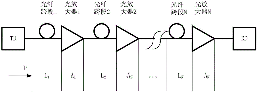
[0021] in corresponding as figure 1 In the system link shown, given the optical path configuration (such as transmitter power, fiber parameters of each segment, amplifier gain of each span, noise index, etc.), assuming that there are N spans in the optical transmission system link, at the receiving end of the system The signal quality parameter (Q value) of (RD) is affected by the input optical power (P) of the system transmitting end (TD), the gain of each amplifier (A n , n=1~N), the length of each span (L n , n = 1 ~ N) and the noise characteristics of each amplifier.

[0022] For example, a method to calculate the system quality parameter (Q value) is to apply cascade calculation of optical signal to noise ratio, that is, Q=SNR Rx . After cascading several sections of fiber with different fiber lengths and different amplifier gains ...


PUM


Abstract

The invention provides an optimization method of transmission performance of a long-distance coherent optical communication system for solving the problem of difficulty in quickly carrying out global optimization on the transmission performance of the coherent optical communication system with a long distance, a large cross-section number, unequal cross-section indexes and no dispersion compensation. The optimization method comprises the following steps that an optimal performance parameter of the whole optical communication link is computed based on link attention and amplifier noise characteristics; ranges and initial values of one group of weighting coefficients (m, t) are arranged; two factors including an optimal difference value of amplifier gain and an amplifier cross-section position are considered to arrange a module Mea (m, t, n), the corresponding Kminth amplifier cross-section position Mk is selected when the Mea is larger, the amplifier gain is Aopt, Mt, wherein k is equal to 1-Kmin, and the other amplifier gain is the initial value thereof. According to the optimization method, promotion of a light path performance index factor Q is considered, instantaneous characteristics, such as shake and time delay, which are caused by overlarge regulated quantity or overlarge regulation number, are avoided, and the performance of the optical transmission system is quickly optimized under the conditions of the extra-long distance and the large cross-section number.

Description

technical field [0001] The invention relates to a method for realizing long-distance optical communication, in particular to a method for optimizing the transmission performance of a coherent optical communication system when the number of spans is large. Background technique [0002] Due to the influence of complex factors such as dispersion, spontaneous gain emission (ASE) noise, and fiber nonlinear effects in optical fiber transmission, the original configuration of link attenuation and gain is often not optimal in dynamic optical path switching scenarios, which limits transmission performance and therefore need to be optimized. The current optical communication system transmission performance optimization scheme is mainly aimed at the direct detection system, including adjusting the transmit power of the source node, adjusting the dispersion compensation and attenuation of the dynamic add-drop multiplexing (ROADM) node, and so on. [0003] Adjust the transmit power sche...

Claims


Application Information

Patent Timeline
Patent Type & Authority Applications(China)
IPC IPC(8): H04B10/293H04B10/564
Inventor 李炜祝唯微金鑫陈宝靖党倩柴京邓捷汪文晋高冠军李圆圆
Owner STATE GRID CORP OF CHINA
Why Eureka
Try Eureka