Linear array micro-nano focus X-ray source for micro-nano CT (computer tomography) system

An X-ray and line array technology, applied in the field of line array micro-nano focus X-ray source devices, can solve the problems that the performance of the micro-focus X-ray source cannot meet its requirements, affect the performance indicators such as the resolution of the CT system, and melt the metal target. Achieve good controllability, avoid errors and prevent overheating

Inactive Publication Date: 2015-03-11
CHONGQING UNIV
View PDF7 Cites 16 Cited by
  • Summary
  • Abstract
  • Description
  • Claims
  • Application Information

AI Technical Summary

Problems solved by technology

[0002] The traditional micro-focus X-ray source generally has only one focal point. For the micro-nano-microsecond fast dynamic digital imaging detection system required in the fields of biology and medicine, the performance of the traditional micro-focus X-ray source cannot meet its requirements.
At present, the micro-focus X-ray source generally has only one focal point. When it is used in a micro-nano CT system, it has the following disadvantages: the scanning of all X-ray projections required for the high-resolution reconstruction of a general micro-nano CT system usually lasts for many Therefore, a large amount of heat will be generated at the same position of the target layer, which may cause the metal target to melt or even be burned; secondly, the micro-focus CT system with one focus uses mechanical scanning, which will inevitably introduce mechanical errors and affect CT System resolution and other performance indicators

Method used


Image

  • Linear array micro-nano focus X-ray source for micro-nano CT (computer tomography) system
  • Linear array micro-nano focus X-ray source for micro-nano CT (computer tomography) system
  • Linear array micro-nano focus X-ray source for micro-nano CT (computer tomography) system

Examples


Embodiment Construction

[0021] The technical solutions in the embodiments of the present invention will be described in detail below in conjunction with the drawings in the embodiments of the present invention. Obviously, the described embodiments are only part of the embodiments of the present invention, not all of them. Based on the embodiments of the present invention, all other embodiments obtained by persons of ordinary skill in the art without making creative efforts belong to the protection scope of the present invention.

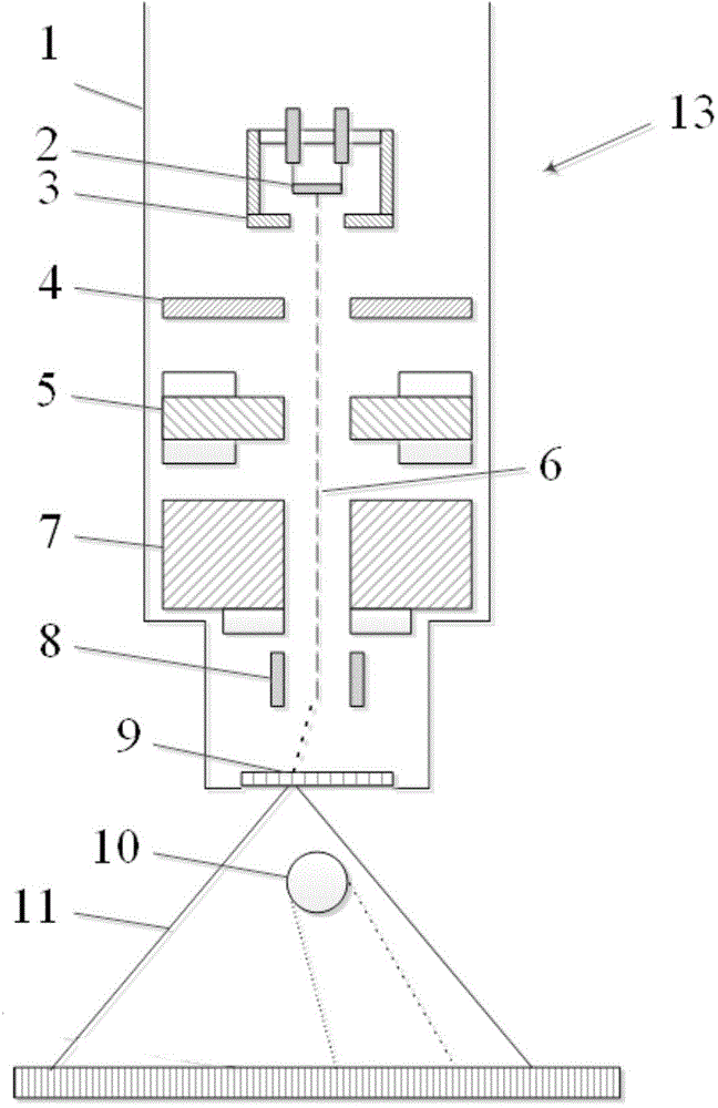
[0022] The invention relates to a line array micro-nano focus X-ray source device, in particular to a line array micro-nano focus X-ray source for a micro-nano CT system.

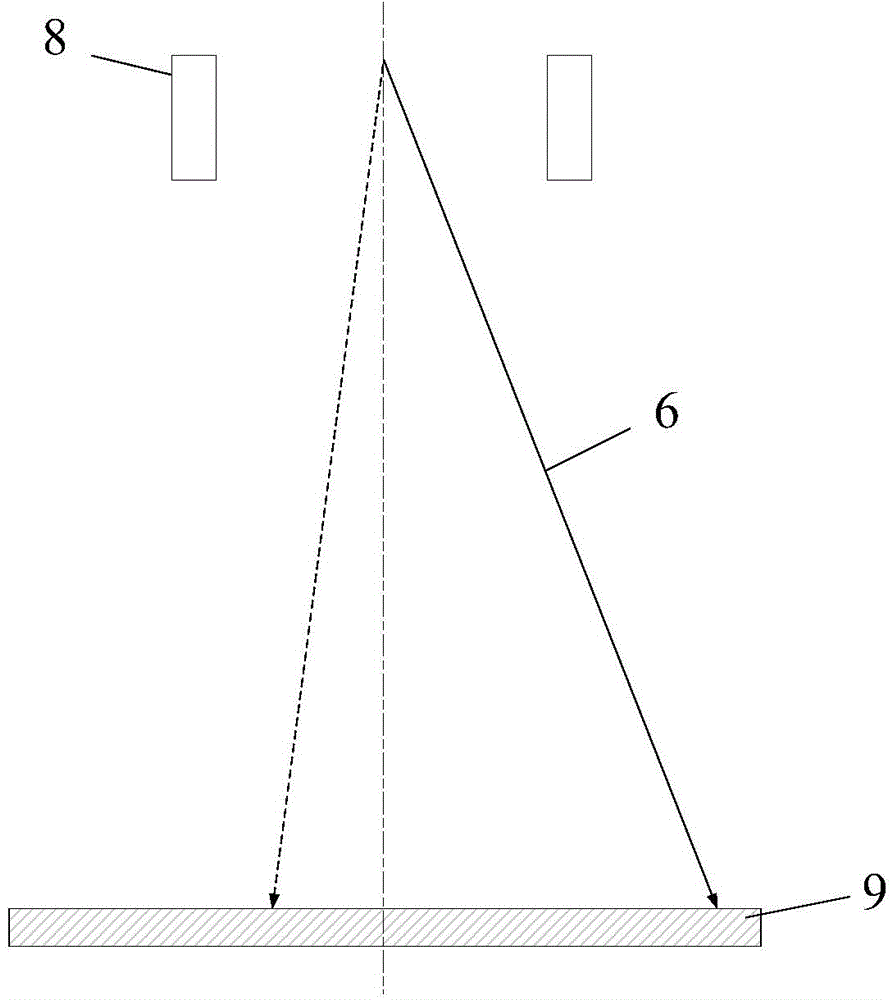
[0023] A line-array micro-nano focus X-ray source 13 for a micro-nano CT system. This X-ray source 13 includes a cathode 2 for generating electrons, an anode 4 for accelerating electrons, and an electron regulator between the cathode 2 and the anode 4. A large number of grids 3, focusing the electron bea...


PUM


Abstract

The linear array micro-nano focus X-ray source for a micro-nano CT system. The linear array micro-nano focus X-ray source for the micro-nano CT system comprises cathodes 2, grids 3, anodes 4, focusing electrodes 5, magnetic solenoids 7, deflecting electrodes 8 and a target 9; the cathodes are used for producing electrons, the anodes are used for electron acceleration, the grids are arranged between the anodes and the cathodes and used for adjusting beam intensity of electron emitted by the cathodes, the focusing electrodes are used for completing first-time focusing of accelerated electrons, the magnetic solenoids are used for completing second-time focusing of the electrons, and the deflecting electrodes are used for controlling the position that the electrons hit on the target. By means of the linear array micro-nano focus X-ray source for the micro-nano CT system, static CT scanning can be achieved, namely, a radiation source, an object to be detected and a detector are all in a static state, electron beam scanning substitutes for mechanical scanning, thus error caused by mechanical scanning can be avoided, small external disturbance, small size, light weight and fast detection speed can be obtained, and linear array micro-nano focus X-ray source for the micro-nano CT system can be applied to CT systems of different types.

Description

technical field [0001] The invention relates to a line array micro-nano focus X-ray source device, in particular to a line array micro-nano focus X-ray source for a micro-nano CT system Background technique [0002] The traditional micro-focus X-ray source generally has only one focal point. For the micro-nano-microsecond level fast dynamic digital imaging detection system required in the fields of biology and medicine, the performance of the traditional micro-focus X-ray source cannot meet its requirements. At present, the micro-focus X-ray source generally has only one focal point. When it is used in a micro-nano CT system, it has the following disadvantages: the scanning of all X-ray projections required for the high-resolution reconstruction of a general micro-nano CT system usually lasts for many Therefore, a large amount of heat will be generated at the same position of the target layer, which may cause the metal target to melt or even be burned; secondly, the micro-fo...

Claims


Application Information

Patent Timeline
Patent Type & Authority Applications(China)
IPC IPC(8): H05G1/52
Inventor 王珏周日峰陈赞向前
Owner CHONGQING UNIV
Why Eureka
Try Eureka