Abrasive flow micropore polishing device and polishing process thereof

A polishing device and abrasive flow technology, applied in abrasive feeding device, used abrasive processing device, abrasive and other directions, can solve the problems of unsafe equipment, difficulty, hydraulic components and pipeline requirements, etc.

Inactive Publication Date: 2015-03-25
GUANGDONG UNIV OF TECH
View PDF4 Cites 34 Cited by
  • Summary
  • Abstract
  • Description
  • Claims
  • Application Information

AI Technical Summary

Problems solved by technology

If the pressure range of conventional abrasive flow equipment is 0.7MPa-22.4MPa, the abrasive flow polishing pressure of 50um holes needs to reach 12.8MPa-411.1MPa, and if it is to polish 30um holes, it will reach 31MPa-995MPa, such a large inlet pressure , it is very difficult to realize it through the hydraulic system, which has extremely high requirements on hydraulic components and pipelines, and under such high pressure, the entire equipment system is extremely unsafe

Method used


Image

  • Abrasive flow micropore polishing device and polishing process thereof

Examples


Embodiment Construction

[0023] Embodiments of the present invention are described in detail below.

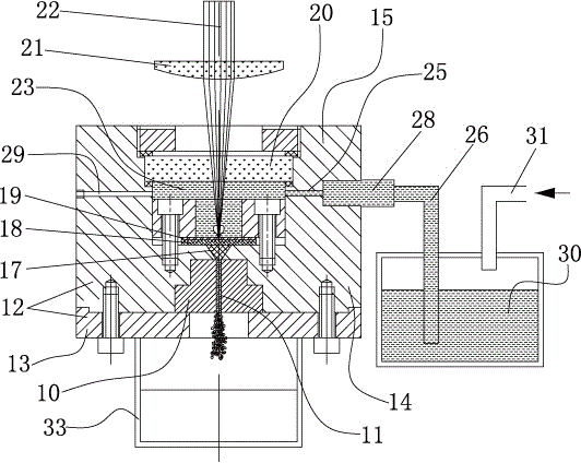
[0024] Such as figure 1 As shown, an abrasive particle flow microhole polishing device of the present invention includes a fixture 12 for clamping a workpiece 10 and positioning the microhole 11 to be polished in the workpiece 10, a base plate 15 installed on the fixture 12, The cavity provided on the inner side of the base plate 15 and the clamp 12 and correspondingly communicated with the microhole 11 of the workpiece 10 is arranged in the cavity to divide the cavity into a cavitation cavity 23 for containing deionized water and a cavity for containing viscose. The spacer of the liquid storage chamber 17 of the elastic abrasive fluid, the laser high-transparency protective mirror 20 covering the side of the cavitation chamber 23 opposite to the workpiece 10, the laser that can generate the laser beam 22 towards the cavitation chamber 23, A focusing lens 21 located between the laser and the laser hi...


PUM


Abstract

The invention discloses an abrasive flow micropore polishing device, comprising a clamping tool, a base plate, a cavity, a separation device, a laser high-transparency protective lens, a laser, a focusing lens, a flow guiding passage and a one-way valve, wherein the clamping tool is used for clamping a workpiece and locating micropores of the workpiece; the base plate is arranged on the clamping tool; the cavity is arranged in the base plate and the clamping tool and correspondingly communicate with the micropores; the separation device is arranged in the cavity and divides the cavity into a cavitation cavity and a liquid storage cavity; the laser high-transparent protective lens covers the cavitation cavity; the laser can generate laser beams facing to the cavitation cavity; the focusing lens is arranged between the laser and the laser high-transparent protective lens and is used for focusing laser beams in the cavitation cavity; the flow guiding passage can guide deionized water into the caviation cavity; the one-way valve is arranged in the flow guiding passage. According to the abrasive flow micropore polishing device, lasers are focused to cavitate the deionized water to form a large local pressure and impact the separation device, and the abrasive fluid flows and is pushed into the micropores at high speed and rubs the pore walls of the micropores to reduce the roughness of the inner surface of the micropores, so as to achieve the polishing on the micropores. The invention further discloses an abrasive flow micropore polishing process for highly effectively and ultra-precisely polishing the micropores.

Description

technical field [0001] The invention relates to precision machining, in particular to an abrasive particle flow microhole polishing device for polishing the inner surface of micropores of metal or nonmetallic hard and brittle materials. The invention also relates to an abrasive flow micropore polishing process for polishing micropores. Background technique [0002] Various micropores are more and more widely used in industries such as aircraft, automobiles, electrical appliances, chemicals, food, and biomedicine. Such as microholes on printed circuit boards, internal combustion engine fuel nozzles, chemical fiber filament nozzles, chopper holes on gold wire ball welding machines, etc. Among them, the minimum diameter of the spray hole of the chemical fiber nozzle is about 10 microns; the minimum diameter of the micropore of the gold wire ball welding machine is about 25 microns. At present, the roughness of the micropore inner surface of these products processed by convent...

Claims


Application Information

Patent Timeline
Patent Type & Authority Applications(China)
IPC IPC(8): B24C3/02B24C7/00B24C9/00B24C1/08
CPCB24C1/08B24C3/02B24C7/0007B24C9/00
Inventor 郭钟宁陈铁牛印四华
Owner GUANGDONG UNIV OF TECH
Why Eureka
Try Eureka