Lower-contact type metro contact rail detecting system

A track detection and detection system technology, which is applied in the direction of railway vehicle shape measuring devices, measuring devices, railway car body parts, etc., can solve problems such as inability to realize off-line analysis and prediction, non-recording of detection data, and problems with brackets, etc., to improve The effect of management level and work efficiency, fast response speed, and avoiding the influence of accidental errors

Inactive Publication Date: 2015-03-25
TIANJIN SINO GERMAN VOCATIONAL TECHN COLLEGE +1
View PDF7 Cites 2 Cited by
  • Summary
  • Abstract
  • Description
  • Claims
  • Application Information

AI Technical Summary

Problems solved by technology

At present, the detection of contact rails is carried out by manual walking and visual inspection, with low detection speed and poor accuracy (the normal walking speed of a person is 3-5KM / hour, and a lot of auxiliary time is needed)
Most of the existing contact rail detection vehicles / devices / systems detect the horizontal and vertical distance between the inner side of the adjacent running rail and the contact rail flow receiving surface, and read the detection data in real time. The detection data is not recorded, stored, or analyzed, which cannot be realized For off-line analysis and prediction, this type of inspection vehicle / device / system is mostly used in the installation of contact rails. For example, a Chinese patent discloses a trolley for detection of contact rails, patent number: 201410226931.3, to ensure the installation quality of contact rails. Mechanical inspection, but this kind of inspection vehicle is used on track installation and is not suitable for later inspection. If it is used in maintenance and repair, when the parameter is detected to be out of tolerance, the bracket has already had a problem

Method used


Image

  • Lower-contact type metro contact rail detecting system

Examples


Embodiment Construction

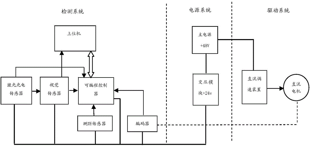
[0016] The specific implementation manner of the present invention will be described in detail below in conjunction with the accompanying drawings and preferred embodiments. Such as figure 1 As shown, a lower-contact subway contact rail track detection system includes a ring encoder, a laser photoelectric sensor, a visual sensor, a laser ranging sensor, a host computer, and detection software. Through signal collection, transmission, storage, and analysis, the Display the detection result. When the detection vehicle moves, the encoder sends out displacement pulses, and the programmable controller reads the encoded position information in real time and transmits it to the host computer to record the running distance or position of the detection vehicle; the laser photoelectric sensor finds the position of the bracket and sends out a pulse signal , trigger the visual sensor to take picture information of the bracket, and trigger the programmable controller to read the position ...


PUM


Abstract

The invention relates to the technical field of rail detection, in particular to a lower-contact type metro contact rail detecting system. The lower-contact type metro contact rail detecting system comprises a detecting system body and a power system used for supplying power to the detecting system body. The detecting system body comprises an encoder, a laser photoelectric sensor, a vision sensor, an upper computer, a distance measuring sensor and a programmable controller. The encoder is connected with the programmable controller, the laser photoelectric sensor is connected with the vision sensor and the programmable controller through signals, and the vision sensor is connected with the upper computer and the programmable controller. The lower-contact type metro contact rail detecting system is simple in structure, detection parameters are visual and effective, a detection method is simple, the response speed is high, and the earlier-stage characters of contact rail faults can be reflected; manual detection is replaced by automatic detection, the number of workers is small, the labor intensity is reduced, and work can be completed only with one person.

Description

technical field [0001] The invention relates to the technical field of track detection, in particular to a lower contact type metro contact rail track detection system. Background technique [0002] The maximum cross-sectional area of ​​the lower contact subway contact rail is about 0.01 square meters, and the single length is about 15 meters. 90-120 meters is a riveting section. In the middle of the riveting section is an expansion joint, and other positions are movable head brackets at intervals of about 5 meters. The length-to-diameter ratio of the contact rail is large, and it is prone to deformation under the influence of factors such as work, ambient temperature, and external force. The initial manifestation of faults caused by the deformation of the contact rail is that the bracket tilts left and right, which in turn leads to damage to the bracket. Therefore, if the problem is found as early as possible in the early stage of bracket deformation, it is of great signif...

Claims


Application Information

Patent Timeline
Patent Type & Authority Applications(China)
IPC IPC(8): B61K9/08G01B11/00G01B11/14
CPCB61K9/08G01B11/16
Inventor 汤晓华范其明李相泉刘赟宇高海娟钱逸秋
Owner TIANJIN SINO GERMAN VOCATIONAL TECHN COLLEGE
Why Eureka
Try Eureka