
Ingot casting furnace and method for preparing silicon ingot

An ingot furnace and silicon ingot technology, which is applied in the field of ingot furnace and silicon ingot preparation, can solve the problems of increased cooling rate of silicon liquid at the side, increased solidification rate of liquid silicon at the side, and increased heat loss at the side, achieving The effect of reducing the probability of sticking pot, reducing the probability of precipitation, and improving the driving force of crystal growth

Active Publication Date: 2017-09-12
YINGLI GRP +2
View PDF11 Cites 0 Cited by
  • Summary
  • Abstract
  • Description
  • Claims
  • Application Information

AI Technical Summary

Problems solved by technology

However, the increase of the heat dissipation port mainly causes the heat loss at the side, so that the heat loss at the side will increase during the crystal growth process, which will increase the cooling rate of the silicon liquid at the side and cause the solidification of the silicon liquid at the side rate increase
At the same time, the crystal growth rate in the center of the silicon ingot will be lower than that in the side of the silicon ingot, so the crystal growth interface will be a concave interface, which will cause the verticality of the crystal direction to decrease, and make the impurities in the center high-quality The area of ​​the silicon block is precipitated, which will increase the impurities in the silicon ingot and reduce the quality of the silicon ingot, which will eventually affect the efficiency of the battery

Method used


Image

  • Ingot casting furnace and method for preparing silicon ingot
  • Ingot casting furnace and method for preparing silicon ingot
  • Ingot casting furnace and method for preparing silicon ingot

Examples


Embodiment Construction

[0025] It should be noted that, in the case of no conflict, the embodiments in the present application and the features in the embodiments can be combined with each other. The present application will be described in detail below with reference to the accompanying drawings and embodiments.

[0026] It should be noted that the terminology used here is only for describing specific implementations, and is not intended to limit the exemplary implementations according to the present application. As used herein, unless the context clearly dictates otherwise, the singular is intended to include the plural, and it should also be understood that when the terms "comprising" and / or "comprising" are used in this specification, they mean There are features, steps, operations, means, components and / or combinations thereof.

[0027] For the convenience of description, spatially relative terms may be used here, such as "on ...", "over ...", "on the surface of ...", "above", etc., to describe...


PUM

PropertyMeasurementUnit
heightaaaaaaaaaa
sizeaaaaaaaaaa

Abstract

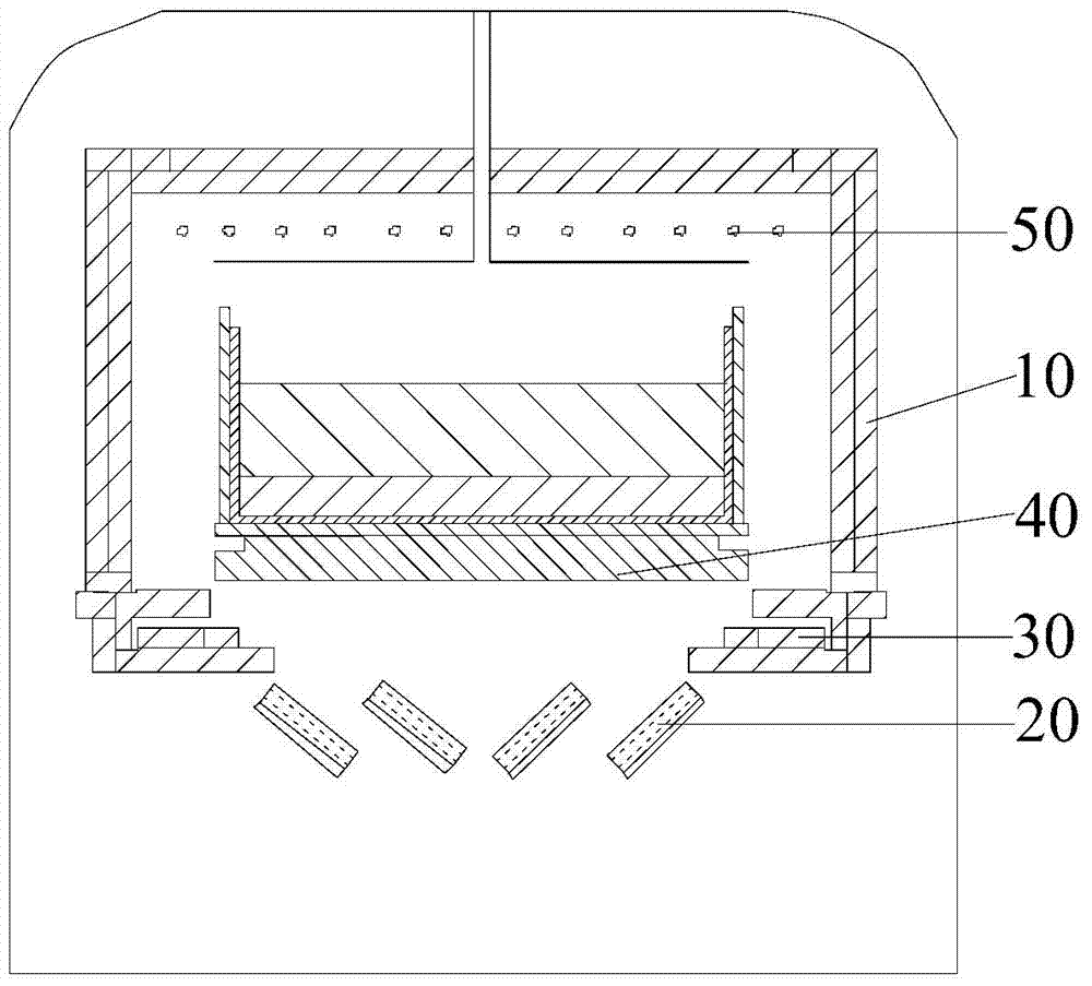
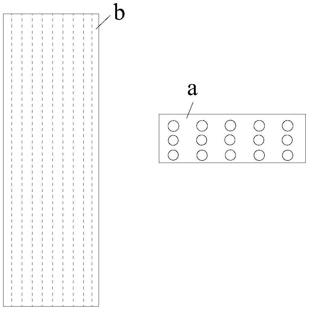
The invention provides a preparation method of an ingot furnace and a silicon ingot. The ingot furnace comprises a thermal insulation cage, a plurality of louvers and baffle plates, wherein a window is formed in the bottom of the thermal insulation cage; the plurality of louvers are arranged below the window; holes which run through the louvers along the direction vertical to the thicknesses of the louvers are formed in the louvers; and the baffle plates are arranged in the thermal insulation cage and are arranged at the bottoms of two side walls of the thermal insulation cage. The heat radiating area of the louvers is increased when the louvers of the ingot furnace are opened, so that the heat radiating rate of the louvers is also increased and the crystal growth drive force at the late growth stage of the silicon ingot is improved. When the ingot furnace adopts a seed crystal process, the heat radiating rate of the bottom of the ingot furnace at a melting stage is increased, and the temperature of the bottom of the ingot furnace is lowered, so that the seed crystal is easy to reserve, and therefore, the quality of the prepared silicon ingot is improved. Meanwhile, the crystal growth drive force at the late growth stage of the silicon ingot is improved, so that the crystal growth rate at the late crystal growth stage is increased, the liquidity of silicon liquid is increased, further fractional condensation of impurities is reinforced, and the outturn percentage is further increased.

Description

technical field [0001] The invention relates to the field of photovoltaic technology, in particular to an ingot casting furnace and a method for preparing silicon ingots. Background technique [0002] Ingot casting furnace is a kind of remelting ingot casting equipment, which is an important process equipment for preparing solar cells and so on. At present, common ingot casting furnaces are generally bottom louver heat dissipation type ingot furnace and side heat dissipation ingot furnace. Wherein, the ingot furnace with heat dissipation at the side (such as GT ingot furnace) realizes heat dissipation at the side of the ingot furnace through the movement of the heat insulation cage at the side. The heat dissipation control of the bottom louver heat dissipation ingot furnace (such as JJL Jinggong ingot furnace) depends on the opening and closing of the louvers at the bottom of the ingot furnace, and there is only one cooling port. Compared with the GT ingot furnace with side...

Claims


Application Information

Patent Timeline
Patent Type & Authority Patents(China)
IPC IPC(8): C30B29/06C30B28/06
CPCC30B28/06C30B29/06
Inventor 王全志孟庆超苏春阳甄良欣张莉沫夏新中潘明翠乔松窦伟军
Owner YINGLI GRP
Learn More