Water treatment control valve

A salt water control valve, control valve technology, applied in the direction of sliding valve, multi-port valve, valve device, etc., can solve the problem of small flow rate of control valve

Active Publication Date: 2015-03-25
WENZHOU RUNXIN MACHINERY MFG
View PDF17 Cites 4 Cited by
  • Summary
  • Abstract
  • Description
  • Claims
  • Application Information

AI Technical Summary

Problems solved by technology

[0008] The technical problem to be solved by the present invention is to provide a water treatment control valve to overcome the defect of low flow rate of the existing planar sealing structure control valve

Method used


Image

  • Water treatment control valve
  • Water treatment control valve
  • Water treatment control valve

Examples


Embodiment 1

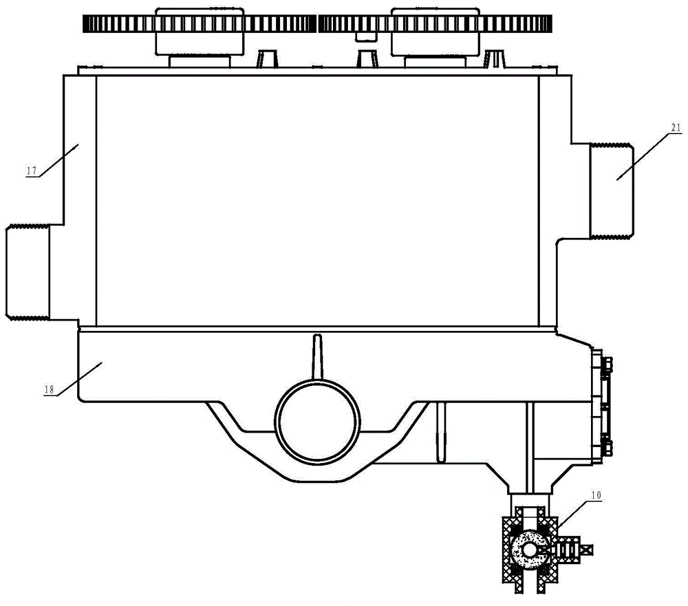
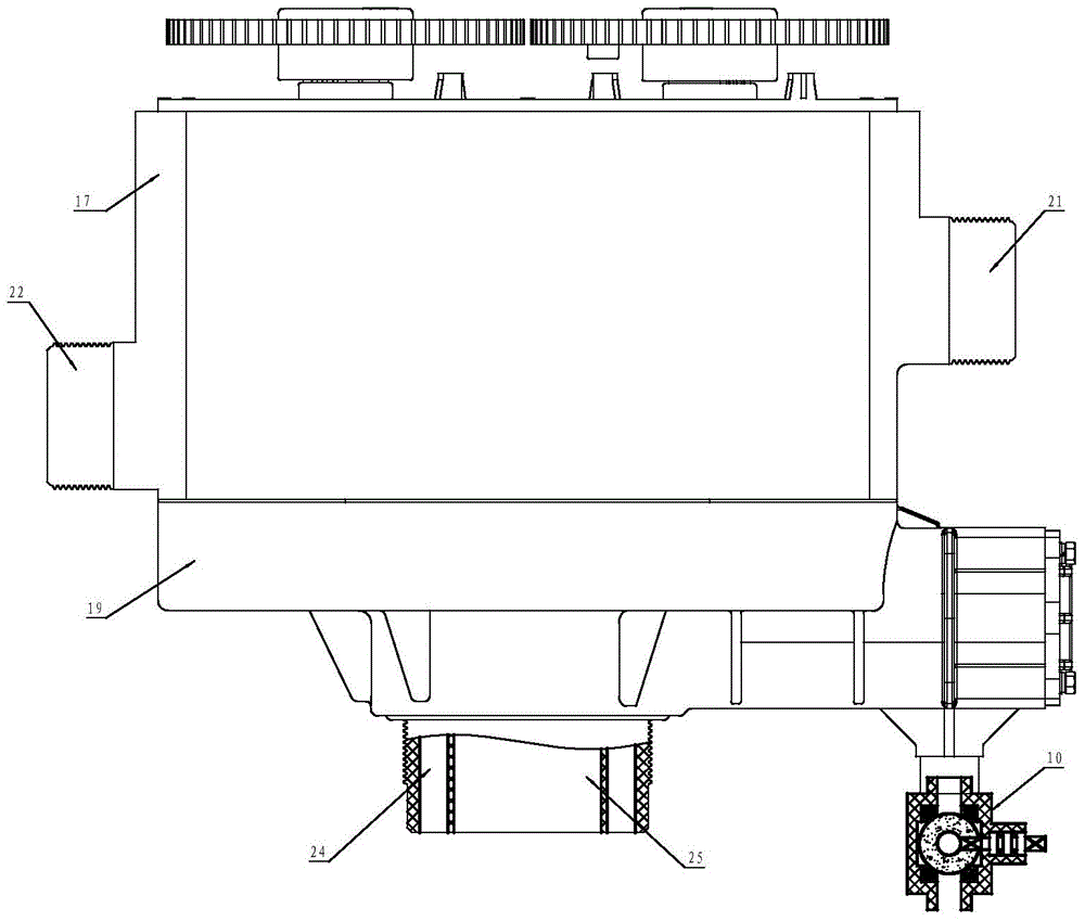
[0080] Example 1: downstream regeneration scheme

[0081] Such as Figure 1-8 As shown, in this embodiment, using Figure 5 and Figure 6 The fixed valve plate and the movable valve plate of the water inlet valve core shown are adopted Figure 7 and Figure 8 The water outlet spool shown is the fixed valve plate and the movable valve plate. In the control valve in Embodiment 1, the valve body 1 is formed by welding or screwing the upper valve body 17 and the lower valve body 18 , and the whole body consisting of the upper valve body and the lower valve body will be introduced below. The valve body 1 is provided with a water inlet 21, a water outlet 22, a drain port 23, an upper filter element interface 24, a filter element lower interface 25, and a branch flow channel 26. The branch flow channel 26 is provided with a jet inlet 27, The ejector outlet 28 normally connected to the filter element upper interface 24, the brine inlet 29, and the brine control valve 10 connected...

Embodiment 2

[0089]Example 2: Countercurrent regeneration and soft water supply scheme

[0090] Such as Figure 22 As shown, in this embodiment, using Figure 5 and Figure 6 The fixed valve plate 5 and the moving valve plate 4 of the water inlet valve core shown are adopted Figure 7 and Figure 8 Shown water outlet valve core fixed valve plate 9 and movable valve plate 8. The valve body 1 is provided with a water inlet 21, a water outlet 22, a drain port 23, an upper filter element interface 24, a filter element lower interface 25, and a branch flow channel 26. The branch flow channel 26 is provided with a jet inlet 27, The ejector outlet 28 normally connected with the filter element lower interface 25, the brine inlet 29, and the brine control valve 10 connected with the brine inlet 29. A water inlet valve core and a water outlet valve core are installed in the valve body 1 . The fixed valve plate 5 of the water inlet valve core is provided with three through holes, the first thro...

Embodiment 3

[0095] Embodiment 3: Floating bed, soft water supply scheme

[0096] The softened water of the floating bed adopts the way of countercurrent operation, and the resin layer filled in the tank of the floating bed is high, so it can handle water with high hardness. Due to the large amount of resin filling, the floating bed has no backwash function, and the regeneration of salt absorption adopts the method of mixed water flow from top to bottom.

[0097] Such as Figure 27 As shown, in this embodiment, using Figure 26 and Figure 6 The fixed valve plate 5 and the moving valve plate 4 of the water inlet valve core shown are adopted Figure 7 and Figure 8 Shown water outlet valve core fixed valve plate 9 and movable valve plate 8. The valve body 1 is provided with a water inlet 21, a water outlet 22, a drain port 23, an upper filter element interface 24, a filter element lower interface 25, and a branch flow channel 26. The branch flow channel 26 is provided with a jet inlet ...


PUM


Abstract

The invention relates to the technical field of water treatment systems, in particular to a water treatment control valve. The water treatment control valve comprises a valve body, an ejector, a water inlet valve spool, a water outlet valve spool and a saline water control valve. The valve body is provided with a water inlet, a water outlet, a water drainage outlet and a salt absorbing branch passageway. The valve body is provided with through holes communicated with an upper part and a lower part of a filter element and an inlet of the ejector. An outlet of the ejector is communicated with the upper part or the lower part of the filter element, the salt absorbing branch passageway is provided with a saline water inlet, and the saline water control valve is arranged at the saline water inlet. A fixed valve block of the water inlet valve spool is provided with three through holes distributed in trisection according to the cross section of the fixed valve block, and a movable valve block is matched with the fixed valve block and provided with a through hole normally communicated with the water inlet. A fixed valve block of the water outlet valve spool is provided with four through holes distributed in quartering according to the cross section of the fixed valve block, and a movable valve block is matched with the fixed valve block and provided with an arc-shaped through blind hole. By different cooperation of the water inlet valve spool, the water outlet valve spool and the saline water control valve, various water treatment functions can be realized, so that a softening valve with water yield exceeding 20 m3 / h can be manufactured.

Description

technical field [0001] The invention relates to the technical field of water treatment systems, in particular to a control valve. Background technique [0002] Existing industrial or civil fluid control (treatment) systems, especially water treatment systems, control the flow of fluid to achieve the soft water system for the purpose of fluid treatment, through a multifunctional softening valve (also called soft water valve, control valve, etc.) , the valve core is used to control the flow direction and flow path of the water flow, and the arrangement and position setting of the water flow channel of the valve is used to switch the flow channel. For the softening system, it is necessary to realize soft water production, backwash, salt absorption regeneration, water replenishment to the salt tank, normal functions such as washing. According to the different regeneration methods, there are two cases of downstream regeneration and countercurrent regeneration; according to the d...

Claims


Application Information

Patent Timeline
Patent Type & Authority Applications(China)
IPC IPC(8): F16K11/074F16K3/314B01D35/02
CPCB01D35/02F16K3/314F16K11/074
Inventor 伍孝荣伍先水丁雄志原海林
Owner WENZHOU RUNXIN MACHINERY MFG
Why Eureka
Try Eureka