Hard bearing dynamic balancing machine precision detection and verifying unit and precision calibration process

A technology of dynamic balancing machine and accuracy detection, which is applied in the direction of static/dynamic balance test, measuring device, machine/structural component test, etc., which can solve the problems affecting the processing and manufacturing of parts, difficult to guarantee accuracy, and uneven skill level and other problems, to achieve the effect of improving operation efficiency, reducing labor intensity and facilitating on-site operation

Active Publication Date: 2015-03-25
CRRC LUOYANG CO LTD
View PDF6 Cites 11 Cited by
  • Summary
  • Abstract
  • Description
  • Claims
  • Application Information

AI Technical Summary

Problems solved by technology

However, this type of hard-supported dynamic balance test equipment has neither a special calibration test device nor a clear and detailed calibration test process after it is delivered to the user. The accuracy of this type of dynamic balance test equipment is out of tolerance, and it also makes users feel at a loss when testing the accuracy of this type of equipment
As a device for testing accuracy, its own accuracy is difficult to guarantee, so the accuracy of the parts to be tested cannot be guaranteed at all, which not only affects the processing and manufacturing of parts, but also affects production and operation, and the downtime due to failures also largely causes dynamics. Balance idle waste of equipment

Method used


Image

  • Hard bearing dynamic balancing machine precision detection and verifying unit and precision calibration process
  • Hard bearing dynamic balancing machine precision detection and verifying unit and precision calibration process
  • Hard bearing dynamic balancing machine precision detection and verifying unit and precision calibration process

Examples


Embodiment Construction

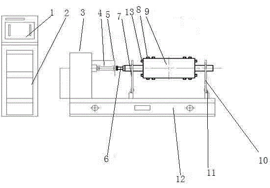
[0030] The present invention is described in conjunction with accompanying drawing and specific embodiment:

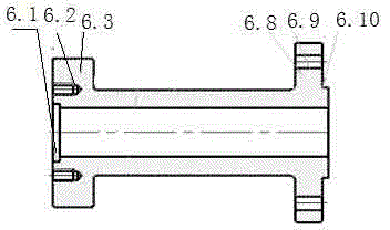
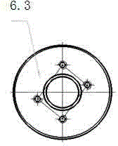
[0031] like figure 1 As shown, a precision detection and verification device for a hard-supported dynamic balancing machine, the precision detection and verification device is connected to the drive device 3 through a universal joint 4, and the drive device 2 is connected to the hard-supported dynamic balancing machine The drive shaft of the universal joint is driven by the driving device 3 to rotate the precision detection and calibration device; the precision detection and calibration device includes a connection flange shaft 6 and a detection calibration calibration mandrel 9; the connection flange The front end of the shaft 6 is connected to the universal joint 4, and the rear end is connected to the detection, verification and calibration mandrel 9, and the detection and verification is realized by connecting the flange shaft 6 and the universal joint transmission...


PUM


Abstract

The invention belongs to the technical field of machinery manufacturing and provides a hard bearing dynamic balancing machine precision detection and verifying unit and a precision calibration process. The precision detection and verifying unit comprises a connection flange shaft (6) and a detection verifying and calibration mandrel (9). The connection flange shaft (6) is connected between a universal coupling (4) and the detection verifying and calibration mandrel (9). The detection verifying and calibration mandrel (9) comprises a balance weight mandrel body (9.4), a front bearing shaft journal (9.3) and a rear bearing shaft journal (9.9), wherein the front bearing shaft journal (9.3) and the rear bearing shaft journal (9.9) are symmetrically arranged on the front end face and the rear end face of the balance weight mandrel body (9.4). The outer diameter face of the balance weight mandrel body (9.4) is provided with two sets of axial plus and minus balance weights (8). The front end face and the rear end face of the balance weight mandrel body (9.4) are provided with radial plus and minus balance weights (13). By means of the hard bearing dynamic balancing machine precision detection and verifying unit and the precision calibration process, the build as well as repair process implementation and product quality of crankshafts are guaranteed, and a technology and quality guarantee is provided for reliable operation of an internal combustion engine and the whole device.

Description

technical field [0001] The invention belongs to the technical field of mechanical manufacturing, and mainly provides an accuracy detection and verification device and an accuracy calibration process of a hard-supported dynamic balancing machine. Background technique [0002] In the manufacture, repair and testing of machinery manufacturing and processing industries and equipment industries, in the manufacture, processing, testing and testing of diesel engine crankshafts, couplings, shock absorbers, axles, wheels and other rotary parts of railway locomotives The adoption of high precision and high speed in the accuracy calibration and verification of equipment must be based on good balance. When the centrifugal force and centrifugal moment caused by different factors appear in different rotating parts, it will often lead to the bearing load. increase, increased wear, vibration and noise, shorten the service life of the machine, and may cause fatigue gaps on the rotating shaft...

Claims


Application Information

Patent Timeline
Patent Type & Authority Applications(China)
IPC IPC(8): G01M1/38
Inventor 辛振奇范豫辉辛苑孔敏张燕军王新航左辉源
Owner CRRC LUOYANG CO LTD
Why Eureka
Try Eureka