
Deep cell super-resolution imaging methods, deep cell super-resolution imaging optical system and prism sheet device

A super-resolution, deep technology, applied in measurement devices, optics, microscopes, etc., can solve problems such as difficulty in photographing biological samples, inconvenience, etc., and achieve the effect of reducing background noise

Active Publication Date: 2015-03-25
THE HONG KONG UNIV OF SCI & TECH
View PDF5 Cites 9 Cited by
  • Summary
  • Abstract
  • Description
  • Claims
  • Application Information

AI Technical Summary

Problems solved by technology

However, due to the geometrical problems of illumination and detection, this technology is still difficult to be applied to photographing more general biological samples.
[0006] In summary, there are obviously inconveniences and defects in the actual use of the existing technology, so it is necessary to improve

Method used


Image

  • Deep cell super-resolution imaging methods, deep cell super-resolution imaging optical system and prism sheet device
  • Deep cell super-resolution imaging methods, deep cell super-resolution imaging optical system and prism sheet device
  • Deep cell super-resolution imaging methods, deep cell super-resolution imaging optical system and prism sheet device

Examples


example 1

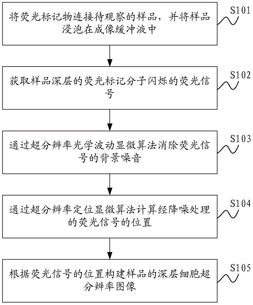
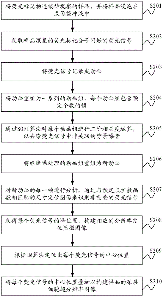
[0129] Example 1: SOFI+LM: When implementing positioning microscopy, first use strong excitation light to make the fluorescent marker molecules on the sample start to blink, and use a CCD (Charge Coupled Device) camera with electron multiplication function to record these blinking The signal is recorded as an animation. The localization software then analyzes each frame of the animation by: (1) identifying non-overlapping scintillation molecules by localizing the image with a size compatible with the desired point spread function, identifying single-molecule Fluorescent signal; (2) Use Gaussian fitting or other methods to obtain the peak position of each blinking fluorescently labeled molecule, construct an LM image from it, perform Gaussian fitting on the identified fluorescent signal and find the center of the signal to locate each Precise location of fluorescently labeled molecules. By superimposing these positions, the final reconstructed super-resolution image can be obt...

example 2

[0135] Example 2: Prism Light Sheet Microscope: The second part of this patent is a novel method of producing light sheet illumination, which can be easily configured on any inverted microscope. Such as Figure 9a As shown, by adding a prism before the illumination objective, not only can the direction of the illumination light be changed, making it perpendicular to the detection objective and providing a large illumination field of view, but also the thickness of the light sheet can be further reduced. Moreover, compared with LSBM, the method of the present invention can be better integrated with commercial microscopes, so the application is simpler, and the imaging resolution can be further improved by using an oil immersion objective lens with a large numerical aperture. Figure 9b It is the result of theoretical calculation, where the compression rate is the ratio of the thickness of the thin slice when there is no prism in the optical path to the thickness when there is a...


PUM


Abstract

The present invention is applicable to optical microscopy and biological cell imaging technology, and provides a deeper cell super-resolution imaging methods, a deep cell super-resolution imaging systems and a prism light sheet device. The first technology program combines the super-resolution optical microscopy fluctuations (SOFI) and super-resolution localization microscopy (IM), so that the cells deep super-resolution image can be used to eliminate non-related background noise coming through the computer operation Get. The first aspect can be directly used in ordinary fluorescent microscope without modifying its original optical structure. A second aspect of light using a prism sheet unit loaded with the inverted microscope, to reduce the background noise by physical means and by positioning microscopy to obtain cells deep super-resolution images to the second aspect can be loaded directly to the traditional inverted fluorescence microscope.

Description

technical field [0001] The invention relates to the fields of optical microscopy technology and biological cell imaging technology, in particular to a method, system and prism light sheet device for super-resolution imaging of deep cells. Background technique [0002] Super-resolution localization microscopy can provide near-molecular-level resolution. The development of this technique has greatly advanced our understanding of intracellular structures. However, in essence, this technology relies on the imaging and precise positioning of a single fluorescently labeled molecule, and requires a very high image SNR (Signal to Noise Ratio, signal-to-noise ratio) to ensure the accuracy of positioning. Localization Microscopy (LM) usually uses Total Internal Reflection (TIRF) or near-TIRF (near-TIRF) methods to reduce background noise by limiting the depth of the illuminated area, so the imaging of this method The area is limited to a few microns above the surface of the sample s...

Claims


Application Information

Patent Timeline
Patent Type & Authority Applications(China)
IPC IPC(8): G01N21/64G02B21/36
CPCG01N15/10G01N21/6458G01N2015/1006G02B21/365G02B27/58
Inventor 雷明德杜胜望赵腾王莹
Owner THE HONG KONG UNIV OF SCI & TECH
Learn More