
Phase change heat storage device and method utilizing engine waste gas waste heat

A phase change heat storage and engine technology, applied in exhaust devices, engine components, combustion engines, etc., can solve the problems of large volume, cold start or long warm-up time, etc., and achieve a small size, simple structure, and easy to start. Effect

Inactive Publication Date: 2015-04-01
BRILLIANCE AUTO
View PDF8 Cites 9 Cited by
  • Summary
  • Abstract
  • Description
  • Claims
  • Application Information

AI Technical Summary

Problems solved by technology

[0004] The object of the present invention is to provide a phase-change heat storage device and method utilizing waste heat of engine exhaust gas, which solves the problems in the prior art that the waste heat device of the engine is too large, and the time for cold start or warm-up is too long. Small, easy to arrange on the vehicle

Method used


Image

  • Phase change heat storage device and method utilizing engine waste gas waste heat
  • Phase change heat storage device and method utilizing engine waste gas waste heat
  • Phase change heat storage device and method utilizing engine waste gas waste heat

Examples


Embodiment 1

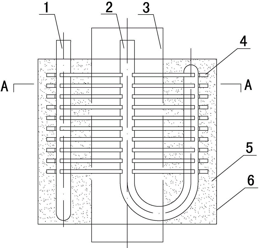
[0023] The phase change thermal storage device utilizing the waste heat of engine exhaust gas in this embodiment, such as figure 1 shown. The device includes hot fluid pipes 3 , heat exchange fins 4 , cold fluid pipes and sleeves 6 . The hot fluid pipeline 3 is connected with the exhaust pipe of the engine, and the heat exchange fin 4 is fixedly connected outside the heat fluid pipeline 3. The edge of the heat exchange fin 4 is provided with a slot, and the cold fluid pipe is clamped in the slot. A sleeve 6 is arranged outside the heat exchange fins 4 and the cold fluid pipe, and a phase change material 5 is arranged between the hot fluid pipe 3 and the sleeve 6 .

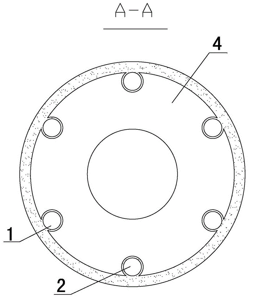
[0024] The cold fluid flows into the phase change heat storage device from the cold fluid inlet 1, and flows out of the phase change heat storage device through the cold fluid outlet 2, such as figure 2 shown.

Embodiment 2

[0026] The difference between the phase change heat storage device of this embodiment and Embodiment 1 is that the heat exchange fins 4 are annular fins.

Embodiment 3

[0028] The difference between the phase change heat storage device of this embodiment and that of Embodiment 1 is that: sleeve heads are provided at both ends of the sleeve 6, and the sleeve 6 and the heads at both ends of the sleeve are welded together. The sleeve and sleeve head are made of stainless steel.


PUM


Abstract

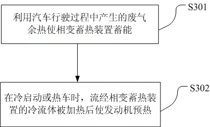
A phase change heat storage device and method utilizing engine waste gas waste heat relates to automobile waste gas and waste heat utilization. The device comprises a warm fluid pipeline, a heat exchange rib, a cool fluid pipeline and a sleeve. The warm fluid pipeline is connected with an engine exhaust pipe, the heat exchange rib is fixedly connected onto the outside of the warm fluid pipeline, a clamping groove is formed in the edge of the heat exchange rib, the cool fluid pipeline is clamped in the clamping groove, the sleeve is arranged on the outside of the heat exchange rib and the cool fluid pipeline, and a phase change material is arranged between the hot fluid pipeline and the sleeve. The device is simple in structure, small in size and convenient to arrange on an automobile. By means of the method, waste gas waste heat generated in the automobile running process is first utilized to enable the phase change heat storage device to store heat. During the cool starting or warming up process, cool fluid flowing through the phase change heat storage device is heated to preheat the engine, and fuel economy in the automobile cool starting and warming up process is improved by heating cooling water in the engine.

Description

technical field [0001] The invention relates to the utilization of exhaust heat of automobiles, in particular to a phase change heat storage device and method for utilizing exhaust heat of an engine. Background technique [0002] Due to the aggravation of energy consumption, the issue of automobile energy saving has received more and more attention. At present, the effective work output by the internal combustion engine only accounts for a small part of the heat released by fuel combustion, while the exhaust gas of the internal combustion engine, as a waste heat, contains a large amount of heat. If the exhaust heat of the internal combustion engine is recovered through waste heat recovery technology, the efficiency of the internal combustion engine will be greatly improved. [0003] At present, the cold start of the car is mainly realized by a separate cold start device, and some cold start devices are realized by controlling the fuel injection volume through a solenoid va...

Claims


Application Information

Patent Timeline
IPC IPC(8): F28D20/02F01N5/02
CPCY02E60/14Y02T10/12
Inventor 马俊达王晖董良卢小锐赖征海李冬梅
Owner BRILLIANCE AUTO
Learn More