Control system and method of bias voltage of IQ optical modulator

A bias voltage, optical modulator technology, applied in the direction of optical fiber transmission, etc., can solve the problems of increasing system complexity and cost, limited practical application range, interference with wavelength channels, etc., and achieves simple structure, convenient and accurate control, and feedback control. simple effect

Active Publication Date: 2015-04-01
HUAZHONG UNIV OF SCI & TECH
View PDF6 Cites 41 Cited by
  • Summary
  • Abstract
  • Description
  • Claims
  • Application Information

AI Technical Summary

Problems solved by technology

[0005] At present, there have been many studies on the control method of modulator bias voltage, such as adding sinusoidal disturbance signals of different frequencies to the DC bias input of each modulator, performing spectrum analysis at the receiving end, and extracting multiple frequencies The relevant data processing operation is carried out to obtain the control information of each bias point. This method needs to generate multiple sinusoidal disturbance signals of different frequencies at the same time, and also needs to do more complex ...

Method used


Image

  • Control system and method of bias voltage of IQ optical modulator
  • Control system and method of bias voltage of IQ optical modulator
  • Control system and method of bias voltage of IQ optical modulator

Examples


Embodiment 1

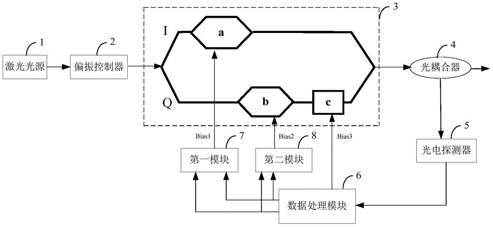
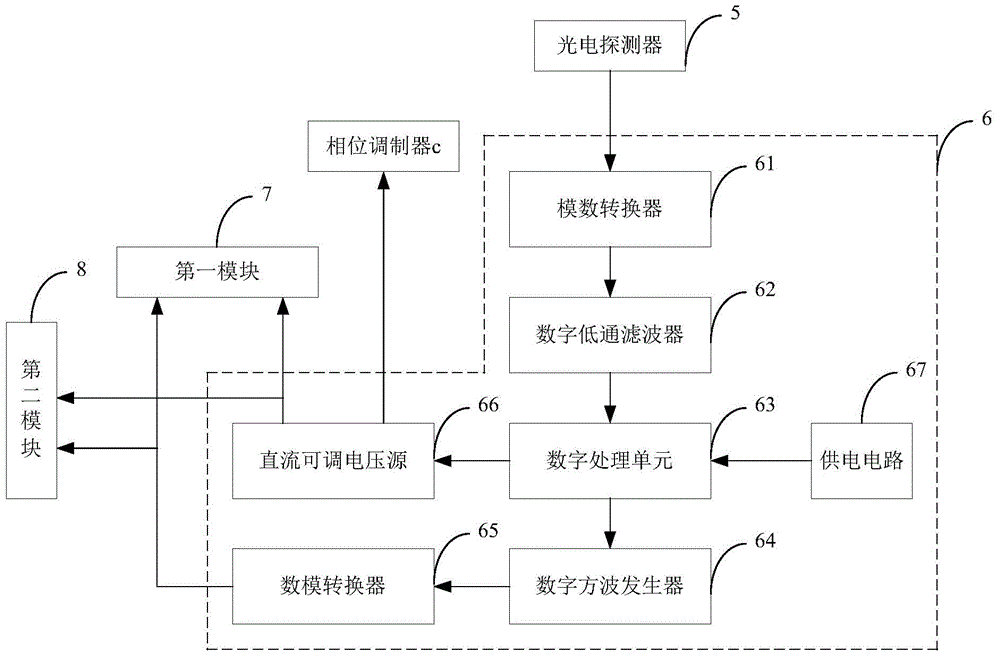
[0054] This embodiment provides a bias voltage control system for an IQ optical modulator, the structure of which is as follows figure 1 As shown, it includes a laser light source 1 , a polarization controller 2 , an IQ light modulator 3 , an optical coupler 4 , a photodetector 5 , and a data processing module 6 connected in sequence. The laser light emitted by the light source 1 passes through the polarization controller 2 to ensure that its polarization state is consistent with that of the IQ optical modulator 3, and then is input to the IQ optical modulator 3. The output of the IQ optical modulator 3 is split by the optical coupler 4 and then connected to the photoelectric The output of the detector 5 and the photodetector 5 are connected to the input of the data processing module 6, and the three outputs of the data processing module 6 are respectively sent to the DC bias voltage inputs of the three sub-modulators a, b, and c of the IQ optical modulator 2 port. The data p...

Embodiment 2

[0057] This embodiment provides the measurement method of the electro-optical phase modulator half-wave voltage measurement system in Embodiment 1, which specifically includes the following steps:

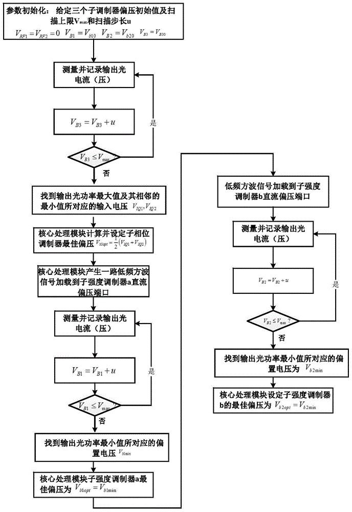
[0058] (1) In the initial state, the RF inputs of the two sub-intensity modulators of the IQ optical modulator are both 0, that is, V RF1 =V RF2 =0, set the DC bias initial value V of the three sub-modulators B1 =V b10 , V B2 =V b20 , V B3 =V b30 , turn on the laser light source, and the data processing module scans the DC bias voltage V of the phase modulator with a certain step size B3 , measure the output optical power of the IQ optical modulator, and record the DC bias voltage V corresponding to the maximum value and the adjacent minimum value of the optical power IQ1 and V IQ2 ; The relevant theoretical derivation of this process is as follows:

[0059] The output light field expression of the IQ light modulator can be written as: in E ...


PUM

PropertyMeasurementUnit
Line widthaaaaaaaaaa
Bandwidthaaaaaaaaaa

Abstract

The invention discloses a control system of bias voltage of an IQ optical modulator and a control method of the bias voltage of the IQ optical modulator. The control system comprises a laser optical source, a polarization controller, the IQ optical modulator, an optical coupler, a photoelectric detector and a data processing module, which are connected in sequence, wherein the output of the IP optical modulator is divided by the optical coupler, and then is connected to the photoelectric detector; the output of the IP optical modulator is connected with the input of the data processing module; three outputs of the data processing module are respectively sent to the direct current bias voltage input ports of three subsidiary modulators of the IQ optical modulator. The control method comprises the steps of optimizing the bias voltage of a subsidiary phase modulator by measuring the maximum value and the adjacent minimum value of an output optical power, loading the minimum value of search optical power of a path of low-frequency square signal onto two subsidiary intensity modulators in sequence to optimize the bias voltages of the two subsidiary intensity modulators on that basis, and finally realizing the control and locking on each subsidiary modulator working point of the IQ optical modulator. By applying the control system and the control method, the perfect bias point of the IQ optical modulator can be rapidly and automatically controlled.

Description

technical field [0001] The invention belongs to the technical field of optical fiber communication, and more specifically relates to a system and method for controlling a bias voltage of an IQ optical modulator. Background technique [0002] With the widespread development of large-bandwidth services such as mobile Internet, cloud computing, 3D TV, high-definition video on demand, telemedicine, and virtual reality, as well as the continuous expansion of the number and scope of broadband network access users, long-distance networks as the backbone of modern communication networks The transmission capacity of the optical fiber communication network will still face huge growth pressure, and put forward higher requirements for the optical transmission system from the network to the device. Coherent optical communication can provide higher receiving sensitivity, apply various high-order modulation patterns, and use digital signal processing (DSP) to balance various optical domain...

Claims


Application Information

Patent Timeline
IPC IPC(8): H04B10/25
Inventor 付松年冯振华唐明刘德明
Owner HUAZHONG UNIV OF SCI & TECH
Why Eureka
Try Eureka