
Full-automatic low-energy-consumption warming system of greenhouse

A fully automatic, low-energy-consumption technology, applied in greenhouse cultivation, energy-saving measures, horticulture, etc., can solve the problems of energy loss, low initial temperature of transmission medium, and high heat, so as to reduce the cost of construction and operation, and flexible installation and adjustment Convenience and simple system structure

Active Publication Date: 2015-04-08
李众彻
View PDF3 Cites 2 Cited by
  • Summary
  • Abstract
  • Description
  • Claims
  • Application Information

AI Technical Summary

Problems solved by technology

[0007] A. Hot air stove: Although the cost is the cheapest, it has high energy consumption, high pollution, and requires people to add coal regularly. At the same time, because of the structure that the hot air dissipates heat through the hot air pipe, the heat near the coal stove is high, and the heat at the end is low. There is a problem of uneven heating and increasing
[0008] B. Coal-fired heating boiler: the advantage is that the heating is even, but the cost is expensive, the energy consumption is medium, the pollution is large, and people need to add coal regularly, it is difficult to popularize and apply in a large area
[0009] C. Electric heating boiler: the advantages are no pollution and uniform heating, but the cost is the highest and the energy consumption is high. It is only used in agricultural demonstration gardens and it is difficult to promote and apply it on a large scale
[0010]In addition, the above three existing greenhouse heating systems do not have the function of heat preservation. The temperature of the water used as the heating transmission medium after starting the heating every night and closing the system in the morning Gradually dissipate, and when the heat preservation curtain is closed at night and the system heating is started again, the water temperature has been greatly reduced compared with the end of heating in the morning, and the initial temperature of the transmission medium is lower for reheating, resulting in greater energy loss

Method used


Image

  • Full-automatic low-energy-consumption warming system of greenhouse
  • Full-automatic low-energy-consumption warming system of greenhouse
  • Full-automatic low-energy-consumption warming system of greenhouse

Examples


Embodiment 1

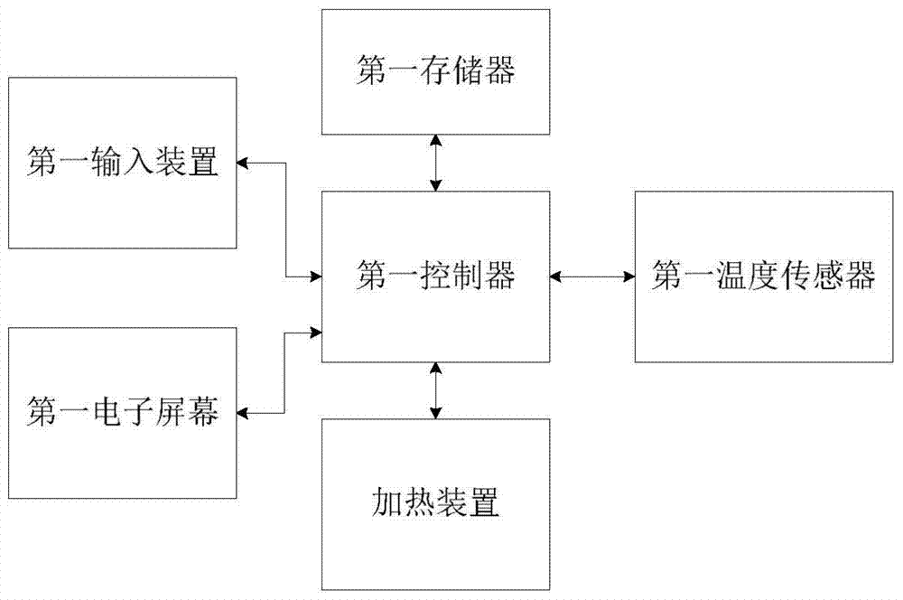
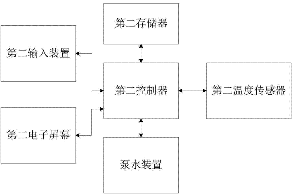
[0057] Example 1: Such as figure 1 As shown, the fully automatic low-energy consumption warming system for greenhouses provided in this embodiment includes an automatic warmer 1, an electric temperature-controlled circulating water pump 2, a water delivery pipe 3, and a cooling fin 4. The automatic warmer 1 includes a stainless steel shell, Stainless steel inner shell, the stainless steel inner shell is a liquid volume chamber, and the insulation layer treated by foaming technology is filled between the stainless steel outer shell and the stainless steel inner shell; The water outlet and the water inlet of the automatic warmer 1; the water outlet of the automatic warmer 1, the electric temperature-controlled circulating water pump 2, several heat sinks 4, and the water inlet of the automatic warmer 1 are connected in sequence through the water delivery pipe 3 to form a heat transfer cycle circuit; the outside of the heat sink 4 is coated with a heat absorbing coating.

[00...

Embodiment 2

[0077] Example 2: The structure is basically the same as that of Embodiment 1, and the similarities are no longer repeated, but the difference is:

[0078] The first temperature sensor includes a room temperature sensor (not shown) arranged outside the stainless steel casing of the automatic warmer 1 for collecting room temperature in the shed (not shown in the figure), and a temperature sensor arranged in the liquid volume chamber of the automatic warmer 1 , a water temperature sensor (not shown in the figure) for collecting the water temperature in the volume chamber; the second temperature sensor includes a room temperature sensor (not shown in the figure) arranged outside the electric temperature-controlled circulating water pump 2 for collecting the room temperature in the shed shown), and a water temperature sensor (not shown in the figure) arranged inside the electric temperature-controlled circulating water pump 2 for collecting the water temperature in the water pump...

Embodiment 3

[0096] Example 3: The structure is basically the same as that of Embodiment 1, and the similarities are no longer repeated, but the difference is:

[0097] In this embodiment, there are 12 aluminum alloy cooling fins connected in sequence, and the volume of the liquid volume chamber is 150L.

[0098] The first temperature sensor only includes a room temperature sensor arranged outside the stainless steel shell of the automatic warmer 1 for collecting the room temperature in the shed; the second temperature sensor only includes a room temperature sensor arranged outside the electric temperature-controlled circulating water pump 2 A room temperature sensor for the room temperature in the collection shed.

[0099] Of course, the first temperature sensor and the second temperature sensor can also share the same room temperature sensor, and the room temperature sensor is connected to the first controller of the automatic temperature increase control system and the second controll...


PUM


Abstract

The invention discloses a full-automatic low-energy-consumption warming system of a greenhouse. The full-automatic low-energy-consumption warming system comprises an electric temperature control circulating water pump, a water conveying pipe, heat radiation sheets and an automatic warming device with a heat preservation function, wherein the automatic warming device is provided with a liquid capacity cavity, a water outlet and a water inlet; the water outlet of the automatic warming device, the electric temperature control circulating water pump, the plurality of heat radiation sheets and the water inlet are connected in sequence by the water conveying pipe to form a heat-transfer cycle loop; heat absorption coatings coat the outer parts of the heat radiation sheets. The starting temperature of repeatedly heating a heat transfer medium is very high through the heat preservation function of the automatic warming device and the heat absorption function of the heat radiation sheets coated with heat absorption materials, so that the energy consumption is extremely saved, the energy efficiency is high and the warming cost is saved. Overall, the full-automatic low-energy-consumption warming system has the advantages of energy conservation, environment friendliness and no pollution, uniformity in warming, low cost and high energy efficiency, full-automatic warming, water conservation, and flexibility and convenience for setting, and can be widely popularized and applied.

Description

technical field [0001] The invention relates to a temperature increasing device, in particular to a device for increasing the temperature of a greenhouse. Background technique [0002] The existing warming technologies for greenhouses mainly fall into the following categories: [0003] A. Hot air stove: It is widely used as a greenhouse to increase the temperature. The structure is a coal stove and an iron ventilation pipe. The principle is that the coal furnace burns coal to generate hot air, and the hot air transports heat through the iron pipe to achieve the effect of warming. [0004] B. Coal-fired heating boilers: generally used by agricultural cooperatives with certain economic conditions. The structure includes a coal-fired high-pressure boiler, a hot water circulation pump, hot water pipes and cooling fins. The principle is that the boiler burns coal to heat water, uses water as the heat transfer medium, and circulates to the radiator through the circulating pump ...

Claims


Application Information

Patent Timeline
Patent Type & Authority Applications(China)
IPC IPC(8): A01G9/24
CPCA01G9/24A01G9/245Y02A40/25Y02P60/14
Inventor 朱炜
Owner 李众彻
Learn More