
Precision gang tool level bed numerically controlled lathe with tailstock

A technology of CNC lathe and flat bed, which is applied in the direction of tailstock/top, automatic lathe/semi-automatic lathe, turning equipment, etc. It can solve the problems of inability to process shaft parts, high failure rate of headstock unit, difficulty in processing and installation, etc. problem, to achieve the effect of simple structure, lower purchase cost and guaranteed quality

Inactive Publication Date: 2015-04-08
杭州万宝数控机床有限公司
View PDF6 Cites 0 Cited by
  • Summary
  • Abstract
  • Description
  • Claims
  • Application Information

AI Technical Summary

Problems solved by technology

Existing CNC lathes with precision row tool and flat bed on the market, adopt X-axis and Z-axis linkage processing, the tool holder is fixed on the small carriage, there is no tailstock, and there is no way to process shaft parts
In addition, most of the spindles in the spindle box units of the precision row tool flat bed CNC lathes on the market directly install the bearings on the spindle box, and most of the clamping mechanisms in the spindle adopt a mechanical lever structure. The failure rate of the spindle box unit is high. Processing , Difficult installation, low precision, short life of spindle bearings, etc.

Method used


Image

  • Precision gang tool level bed numerically controlled lathe with tailstock
  • Precision gang tool level bed numerically controlled lathe with tailstock
  • Precision gang tool level bed numerically controlled lathe with tailstock

Examples


Embodiment Construction

[0015] The present invention will be further described below in conjunction with the accompanying drawings.

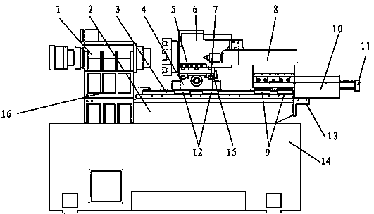
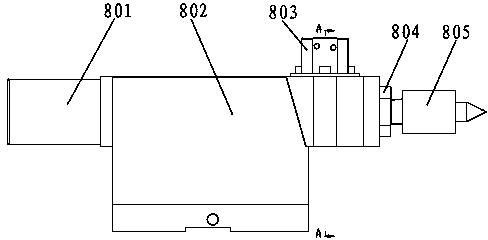
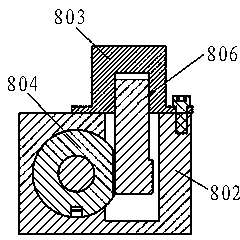
[0016] As shown in the figure, a CNC lathe with a precision row of tailstocks and a flat bed includes a base 14 on which a headstock seat 16 is fixed, and a headstock unit 1 is fixed on the headstock seat 16 . The spindle box unit 1 includes a spindle box 105 and a spindle unit 107 arranged in the spindle box 105, a spindle pull rod 108 is arranged in the spindle unit 107, a pneumatic rotary cylinder 101 is fixedly arranged at the rear end of the spindle unit 107, and an elastic collet is fixedly arranged at the front end of the spindle pull rod 108 106 , the rear end of the main shaft pull rod 108 is fixedly connected with the cylinder piston 109 of the pneumatic rotary cylinder 101 through the provided connecting nut 102 . The main shaft unit 107 includes a main shaft 1075 and a main shaft sleeve 1073 sleeved outside the main shaft 1075. The front and rear ends of th...


PUM


Abstract

The invention relates to a precision gang tool level bed numerically controlled lathe with a tailstock and belongs to the technical field of metal cutting machine tools. The lathe comprises a base, wherein a headstock seat and a bed are fixedly arranged on the base; a headstock unit is fixedly arranged on the headstock seat; a Z-axis linear rail and a Z-axis lead screw are fixedly arranged on the bed; a first Z-axis linear rail slide block is arranged on the Z-axis linear rail in a sliding fit manner; a middle planker is fixedly arranged on the first Z-axis linear rail slide block and connected with the Z-axis lead screw; an X-axis linear rail and an X-axis lead screw are fixedly arranged on the middle planker; an X-axis linear rail slide block is arranged on the X-axis linear rail in a sliding fit manner; a small planker is fixedly arranged on the X-axis linear rail slide block and connected with the X-axis lead screw; a multistation cutter turret is fixedly arranged on the small planker; a second Z-axis linear rail slide block is arranged on the Z-axis linear rail in a sliding fit manner; a tailstock unit is fixedly arranged on the second Z-axis linear rail slide block; and the bottom of the tailstock unit is connected with a hydraulic tailstock push cylinder. The lathe has positive significance for popularization of the numerically controlled machine tools.

Description

technical field [0001] The invention belongs to the technical field of metal cutting machine tools, and in particular relates to a CNC lathe with a tailstock and a precision-arranged flat bed. Background technique [0002] CNC lathes are commonly used machine tools in machining. Existing CNC lathes on the market with precision row tool and flat bed adopt X-axis and Z-axis linkage processing, the tool holder is fixed on the small carriage, there is no tailstock, and there is no way to process shaft parts. In addition, most of the spindles in the spindle box units of the precision row tool flat bed CNC lathes on the market directly install the bearings on the spindle box, and most of the clamping mechanisms in the spindle adopt a mechanical lever structure. The failure rate of the spindle box unit is high. Processing , The installation is difficult, the precision is low, and the life of the main shaft bearing is short. Contents of the invention [0003] Aiming at the probl...

Claims


Application Information

Patent Timeline
IPC IPC(8): B23B7/14B23B23/00
CPCB23B7/12B23B23/00
Inventor 李永良杨春祥
Owner 杭州万宝数控机床有限公司
Learn More