
A claw pole of an automobile generator and its manufacturing process

A technology of automobile generator and manufacturing process, which is applied in the direction of manufacturing tools, manufacturing motor generators, electromechanical devices, etc., can solve the technical requirements that the wall thickness of magnetic bars cannot be uniform, it is difficult to have uniform wall thickness of magnetic bars, and the effect of fixing magnets Poor and other problems, to achieve the effect of good product consistency, uniform wall thickness and consistent size

Active Publication Date: 2017-01-11
TAIZHOU BAIDA ELECTRICAL APPLIANCE CO LTD
View PDF12 Cites 0 Cited by
  • Summary
  • Abstract
  • Description
  • Claims
  • Application Information

AI Technical Summary

Problems solved by technology

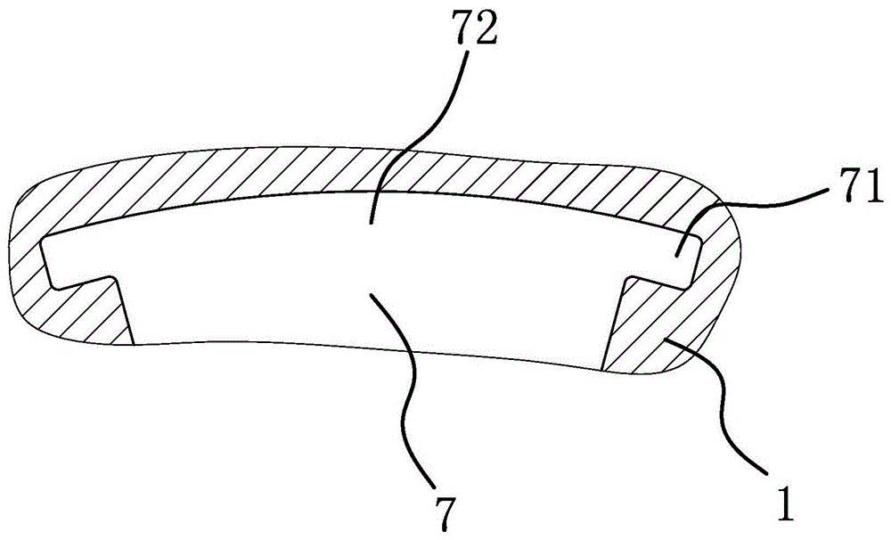
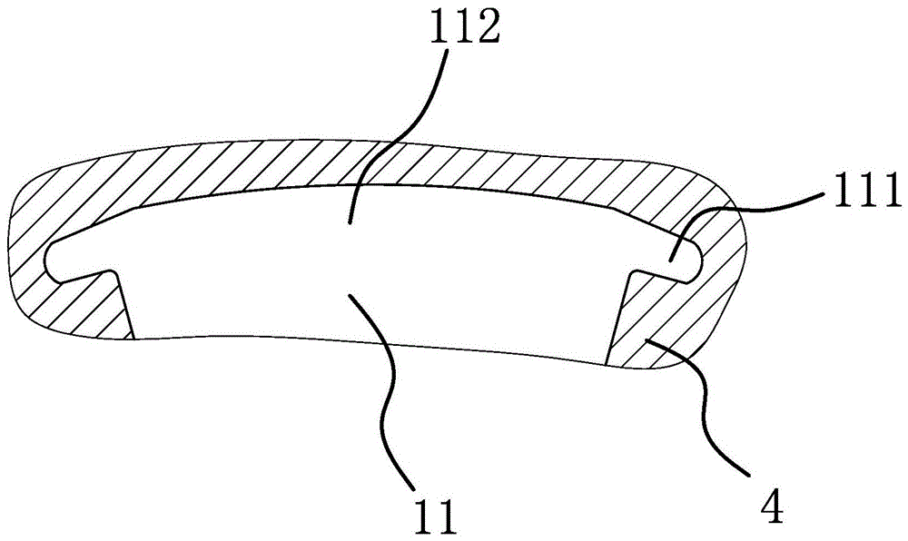
[0004] In the claw pole processing technology of this structure, a claw pole has 6 or 8 vertical claws, and the magnet placement slots are located on both sides of the vertical claws, and are milled out by a T-shaped milling cutter. It takes 12 hours to complete the processing of a claw pole. Cutting the magnet placement groove once or 16 times, this processing method takes a long time to process a claw pole, which is time-consuming and laborious, and the processing efficiency is low; and in the process of processing, it is difficult to ensure that the wall thickness of the magnetic bars on both sides of the magnet placement groove is uniform, The technical requirements of consistent wall thickness of the magnetic ribs cannot be met, that is, after the magnet is placed in the magnet placement slot, the magnet has the problem of looseness when rotating, and the stability is poor; and the final completion is affected by factors such as tools, fixtures, and cutting volume. It is difficult to form a unified standard for the size and accuracy of the magnet placement slot, which increases the difficulty of subsequent processing and even causes scrapping of parts
Moreover, for the claw pole of this structure, the magnet placement groove is located above the bottom plane, and the inner wall of the magnet placement groove near the yoke is relatively short, and the top is thin, which is easy to collapse, and the effect of fixing the magnet is poor, which may easily lead to the scrapping of the claw pole.

Method used


Image

  • A claw pole of an automobile generator and its manufacturing process
  • A claw pole of an automobile generator and its manufacturing process
  • A claw pole of an automobile generator and its manufacturing process

Examples


Embodiment 1

[0054] Such as figure 1 As shown, the manufacturing process of the claw pole of the automobile generator includes the following steps:

[0055] a. Blank forming: use a shearing machine to cut the bar, heat the sheared bar to 1160-1240°C with an intermediate frequency furnace, use a die forging machine to forge the heated bar to form a blank, and use a press to shape the blank flash cut off;

[0056] b. Heat treatment: Use a mesh belt furnace to heat treat the blank, so that the hardness of the blank is 90-160HV5, and the grain size is 6-8;

[0057] c. Shot blasting and shaping: Use a shot blasting machine to remove the scale on the surface of the heat-treated blank, and then use a hydraulic oil press to shape the blank;

[0058] d. Phosphorus saponification: Phosphorus saponification is carried out on the blank after shaping, so that the surface of the blank has a phosphorus saponification layer;

[0059] e. Cold shaping one: put the blank that has been saponified by phosph...

Embodiment 2

[0068] like Figure 11 As shown, the process flow and structure of this embodiment are basically the same as that of Embodiment 1, the difference is that in this embodiment, four drainage grooves 16 and two positioning key grooves are evenly distributed on the circumferential edge of the yoke 10 18. Two positioning key grooves 18 are arranged symmetrically around the bottom plate 5. The positioning key grooves 18 are used to facilitate the positioning of the claw pole 20 during finishing. The drainage groove 16 is connected to the arc groove 15 through the lead-out wire groove 17 or the positioning key groove 18 , and there is no coil anti-rotation protrusion 19 in the structure of this embodiment.


PUM

PropertyMeasurementUnit
thicknessaaaaaaaaaa
widthaaaaaaaaaa
lengthaaaaaaaaaa

Abstract

The invention provides an automobile generator claw pole and a manufacturing process thereof, belongs to the technical field of automobile generators, and solves the problems that the existing claw pole is troublesome to manufacture, and after the existing claw pole is manufactured, magnetic ribs are low in precision, and the like. The manufacturing process comprises the following steps: a, forming a blank ; b, thermally treating; c, performing shot blasting, and shaping; d, phosphorus-saponifying; e, performing cold shaping primarily; f, performing cold shaping secondarily; g, finishing. The automobile generator claw pole comprises a bottom plate, wherein vertical claws are uniformly distributed on the edge of the bottom plate; a magnetic yoke is further arranged in the middle of the bottom plate; the vertical claws and the magnetic yoke are arranged on the same side of the bottom plate; the bottom cross sections of the vertical claws are larger than top cross sections of the vertical claws in size; magnetic ribs are arranged on the two sides of the outer side surface of each vertical claw in an inclined way; the magnetic ribs are raised out of the left side surface and the right side of each vertical claw; the magnetic ribs and the corresponding vertical claw form an integral structure; positioning slots are formed in the two sides of each vertical claw; the positioning slots are formed in the bottom plate. By the manufacturing process, the claw pole manufacturing efficiency and the claw pole manufacturing precision are high.

Description

technical field [0001] The invention belongs to the technical field of automobile generators, and relates to a claw pole of an automobile generator and a manufacturing process thereof. Background technique [0002] With the development of society and the improvement of people's living standards, cars have gradually become the main means of transportation for people to travel, and people's requirements for the comfort of cars are getting higher and higher. The power consumption of electrical components such as adjustable seats has risen sharply, and the requirements for generator power are also getting higher and higher. For this reason, people have invented claw pole generators, and permanent magnets are embedded between the front and rear claw poles of the generator, greatly Increase the magnetic permeability of the claw poles, thereby greatly increasing the output power and efficiency of the generator. [0003] The existing generator claw pole processing technology, for e...

Claims


Application Information

Patent Timeline
Patent Type & Authority Patents(China)
IPC IPC(8): B23P15/00H02K15/00
CPCB21D37/10B21J5/002B23P15/00H02K1/06
Inventor 汪超张启春牛祥永叶学斌张明涛
Owner TAIZHOU BAIDA ELECTRICAL APPLIANCE CO LTD
Learn More