Hydraulic extruding material supplying system and hydraulic extruding material supplying method for 3D bioprinting

A 3D printing and feeding system technology, applied in the field of tissue engineering scaffold 3D printing and biological 3D printing hydraulic extrusion feeding system, to achieve the effect of compact structure, low accuracy of excluding feeding, and real-time control.

Active Publication Date: 2015-04-08
SHANGHAI UNIV
View PDF4 Cites 7 Cited by
  • Summary
  • Abstract
  • Description
  • Claims
  • Application Information

AI Technical Summary

Problems solved by technology

However, it is rarely used in current bio-3D printing equipment, especially extrusion feeding devices, b

Method used


Image

  • Hydraulic extruding material supplying system and hydraulic extruding material supplying method for 3D bioprinting
  • Hydraulic extruding material supplying system and hydraulic extruding material supplying method for 3D bioprinting
  • Hydraulic extruding material supplying system and hydraulic extruding material supplying method for 3D bioprinting

Examples


Embodiment 1

[0030] A hydraulic extrusion feeding method utilizing a hydraulic extrusion feeding system for biological 3D printing, comprising the following steps:

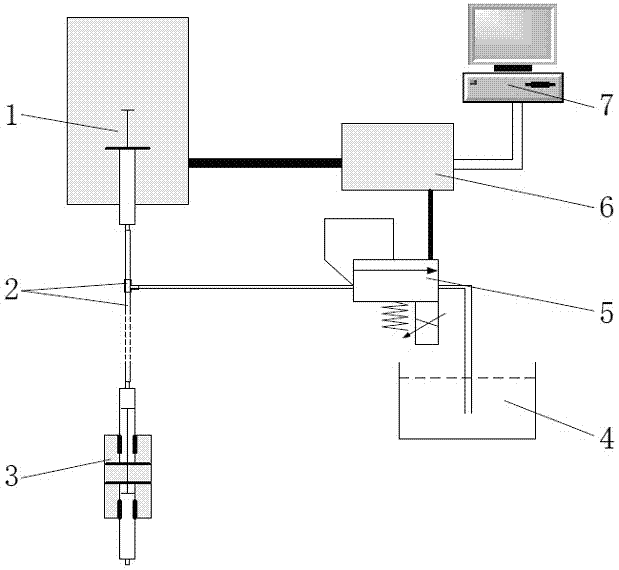
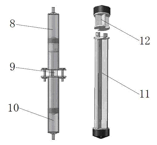
[0031] Prepare 20% gelatin aqueous solution and 5% chitosan solution, mix to obtain gelatin-chitosan mixed solution 10ml, leave standstill to obtain stable and uniform hydrogel solution, pack in the feeding chamber 10, and be installed in the nozzle device 3, Assembling hydraulic feeding systems such as figure 1 Shown; Start the micro-injection pump and the electro-hydraulic proportional overflow valve 5 by the host computer 7, control the feeding rate of the micro-injection pump to be 400ul / min and the regulating pressure of the electro-hydraulic proportional overflow valve 5 to be 200KPa, so that the hydrogel The material is extruded and the bracket is printed according to the processing path; after the printing of a layer of bracket is completed, the regulating pressure of the electro-hydraulic proportional overflow valve 5...

Embodiment 2

[0033] A hydraulic extrusion feeding method utilizing a hydraulic extrusion feeding system for biological 3D printing, comprising the following steps:

[0034] In the hydraulic extrusion feeding system, two nozzle devices are connected through a two-position three-way solenoid valve, such as Figure 4Shown; prepare 20% gelatin aqueous solution and 5% chitosan solution, mix to obtain gelatin-chitosan mixed solution 10ml, stand to obtain stable and uniform hydrogel solution; configure 5% sodium alginate aqueous solution 10ml, stand Obtain a stable and uniform hydrogel solution; put the two materials into two nozzle devices respectively; start the micro-injection pump and the electro-hydraulic proportional overflow valve 5 through the host computer 7, and control the feeding rate of the micro-injection pump to be 400ul / The control pressure of min and electro-hydraulic proportional overflow valve 5 is 200KPa; the two-position three-way solenoid valve is first connected to the noz...


PUM


Abstract

The invention relates to hydraulic extruding material supplying system and a hydraulic extruding material supplying method for 3D bioprinting. The hydraulic extruding material supplying system comprises a pressure source, a liquid pipe, a spray head device, a liquid storage box, a electrohydraulic proportional overflow valve, a controller and an upper computer, wherein the pressure source comprises a micro-injection pump and a medical injector; the liquid pipe is connected with the spray head device, the liquid storing box and the electrohydraulic proportional overflow valve to form an extruding circuit and a pressure regulating circuit; the controller is connected with the micro-injection pump and the electrohydraulic proportional overflow valve through data wires and is used for controlling the work of the whole hydraulic material supplying system through the upper computer. With the adoption of the hydraulic extruding material supplying system and the hydraulic extruding material supplying method for 3D bioprinting, the material extrusion can be controlled in real time and can quickly respond; the system and the method are applicable to various extrusion molding 3D bioprinting devices and are not limited by materials and processes.

Description

technical field [0001] The invention relates to a 3D printing forming technology for tissue engineering scaffolds, in particular to a hydraulic extrusion feeding system and method for biological 3D printing, belonging to the technical field of biological manufacturing. Background technique [0002] 3D printing technology is a new type of processing and forming technology that uses the accumulation of materials layer by layer to build three-dimensional shapes from scratch. Nowadays, it is more and more used in processing and manufacturing and rapid modeling. In the field of biomanufacturing and tissue engineering, the technical advantages of 3D printing are more prominent, and the application is more extensive. Due to the excellent performance of tissue engineering scaffolds for tissue repair devices, extensive research has been done on their manufacturing methods, including freeze-drying, particle leaching, and mold casting. Among them, the extrusion molding method can be u...

Claims


Application Information

Patent Timeline
IPC IPC(8): B29C67/00B29C47/92B29C48/92
Inventor 刘媛媛梁刚李瑜江郑龙胡庆夕
Owner SHANGHAI UNIV
Why Eureka
Try Eureka