
Compression roller for flat-die biomass molding machine and ceramic layer growth method of compression roller

A technology of biomass forming machine and growth method, which is applied in the field of pressure rollers and ceramic layer growth of flat die biomass forming machines, which can solve the problems of short service life, poor wear resistance, poor applicability, etc., and achieve long wear life , Good wear resistance and good applicability

Active Publication Date: 2015-04-08
SHANDONG PROVINCE JINING CITY TONGJI MACHINERY
View PDF12 Cites 0 Cited by
  • Summary
  • Abstract
  • Description
  • Claims
  • Application Information

AI Technical Summary

Problems solved by technology

[0004] The present invention aims to solve the problems of poor applicability, high cost, poor wear resistance and short service life of the pressure roller used in the flat-die biomass forming machine, and further provides a pressure roller for the flat-die biomass forming machine and the structure of the pressure roller Ceramic layer growth method

Method used


Image

  • Compression roller for flat-die biomass molding machine and ceramic layer growth method of compression roller
  • Compression roller for flat-die biomass molding machine and ceramic layer growth method of compression roller

Examples


specific Embodiment approach 1

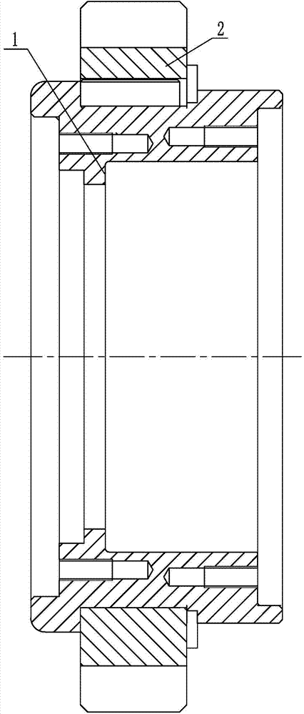
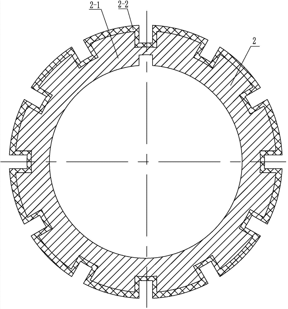
[0018] Specific implementation mode one: combine Figure 1-Figure 2 Explain that the pressure roller for a flat die biomass molding machine in this embodiment is mainly composed of a roller body 1 and a ring gear 2. The ring gear 2 is fitted on the roller body 1 through a key. The ring gear 2 is mainly composed of a base 1 and the alumina ceramic layer 2-2 on the surface of the substrate, the surface of the substrate 2-1 adopts micro-arc oxidation to form the alumina ceramic layer 2-2, the substrate 2-1 is made of aluminum or aluminum alloy material, and the alumina ceramic layer 2-2 has a thickness of 40 microns to 120 microns.

[0019] The teeth of the ring gear of the present embodiment are ring gears arranged on the outer side.

specific Embodiment approach 2

[0020] Specific implementation mode two: combination Figure 1-Figure 2 Note that the aluminum alloy described in this embodiment is LC9 aluminum alloy or LY12 aluminum alloy. With such setting, the hardness is high, the composition is reasonable, the comprehensive performance is good, and it can be strengthened by heat treatment. Others are the same as in the first embodiment.

specific Embodiment approach 3

[0021] Embodiment 3: The alumina ceramic layer 2-2 in this embodiment is mainly composed of a loose layer, a dense layer and a transition layer, the dense layer is located between the loose layer and the transition layer, and the transition layer is arranged close to the substrate 2-1. In this way, the loose layer is exposed to the dense layer after being worn out, and the dense layer has high hardness and wear resistance and can resist the wear of the material. Therefore, it can not only overcome the problems of severe wear and low service life of the integral metal bushing, but also solve the problem that the integral ceramic material cannot guarantee the machining accuracy and is easily broken. Others are the same as in the first or second embodiment.


PUM

PropertyMeasurementUnit
thicknessaaaaaaaaaa
Knoop hardnessaaaaaaaaaa
thicknessaaaaaaaaaa

Abstract

The invention discloses a compression roller for a flat-die biomass molding machine and a ceramic layer growth method of the compression roller, and relates to the compression roller for the flat-die biomass molding machine and the ceramic layer growth method, which are used for solving the problems of poor applicability, high cost, poor abrasion resistance and short service life of the compression roller of the flat-die biomass molding machine. The compression roller mainly comprises a roller body and a gear ring, wherein the gear ring sleeves the roller body via a key; the gear ring mainly comprises a base body and an aluminum oxide ceramic layer on the surface of the base body; the aluminum oxide ceramic layer is generated on the surface of the base body via micro-arc oxidation; the base body is an aluminum or aluminum alloy material. The compression roller for the flat-die biomass molding machine and the ceramic layer growth method of the compression roller are applied to flat-die biomass molding machines.

Description

technical field [0001] The invention relates to a pressure roller for a flat-die biomass molding machine and a ceramic layer growth method, in particular to a ring-gear type pressure roller for a flat-die biomass molding machine with a micro-arc oxidation ceramic layer and a ceramic layer growth method for the pressure roller. Background technique [0002] Biomass molding machine is a kind of mechanical equipment that converts waste straw into combustible biomass energy. It mainly uses pressure to press and shape straw to make it a fuel with high calorific value. It can not only solve the environmental pollution caused by farmers burning straw , and can become a renewable energy that can replace fossil fuels such as coal. However, due to the huge pressure on the straw during the molding process and repeated rolling, the pressure roller has been in intense friction with the straw raw material during the rolling process, the pressure roller of the forming machine is worn out r...

Claims


Application Information

Patent Timeline
Patent Type & Authority Applications(China)
IPC IPC(8): C25D11/04B30B15/00B32B18/00B32B15/04
CPCB30B11/208
Inventor 曲建俊郑杨
Owner SHANDONG PROVINCE JINING CITY TONGJI MACHINERY
Learn More