
Low power consumption electric valve

An electric valve, low power consumption technology, applied in the direction of sliding valves, lift valves, valve details, etc., can solve the problems of unstable performance of electric valves, increased opening and closing force, and failure of drainage valves, etc., to achieve water supply and circulation Good performance, small fluid pressure loss, and the effect of overcoming fouling and sticking

Active Publication Date: 2016-08-24
刘庆荣
View PDF5 Cites 0 Cited by
  • Summary
  • Abstract
  • Description
  • Claims
  • Application Information

AI Technical Summary

Problems solved by technology

Traditional electric valves have the following disadvantages: 1. The spherical switch or cylindrical switch has a large opening and closing force and high power consumption
2. The structure of the drainage valve is complex, there are many metal components, and the manufacturing cost is high
3. Key parts such as the metal parts of the drain valve and the spherical or cylindrical switches of the electric actuator are immersed in water for a long time to work, the surface is easy to rust and scale, the smoothness decreases, and the failure rate is high.
Corrosion and scaling on the surface of spherical or cylindrical switches will increase the force of opening and closing the door, and the power consumption will increase. It will also cause the inflow and outflow fluids in the control pipeline to leak and collude with each other due to the decline in the finish of the switch, making the drain valve The pressure difference between the pressure of the water inlet chamber below and the pressure control chamber of the upper part of the drain valve is out of alignment, and the drain valve fails to work; the metal components of the drain valve are corroded and scaled, which will cause the valve core to be stuck, and the electric valve cannot work normally.
4. The sealing effect between the water inlet chamber and the water outlet chamber of the drainage valve is poor, and the water inlet chamber and the water outlet chamber are not tightly sealed, which makes the electric valve work performance unstable, and the water supply pipeline is inaccurately closed

Method used


Image

  • Low power consumption electric valve
  • Low power consumption electric valve
  • Low power consumption electric valve

Examples


Embodiment Construction

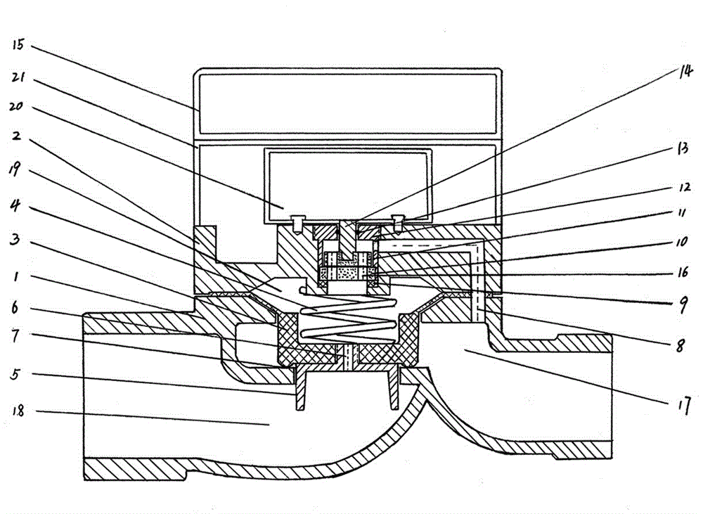
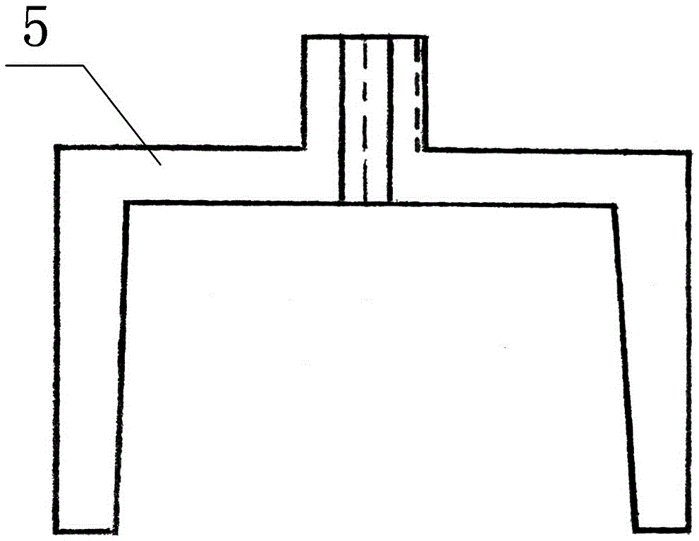
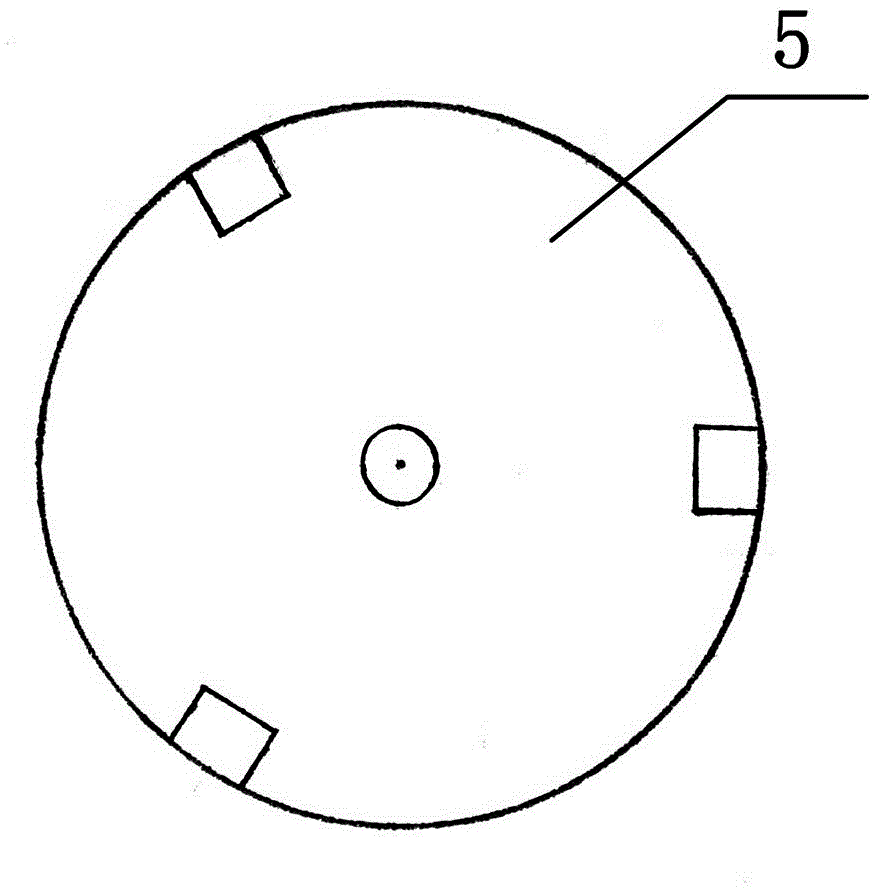
[0014] Such as figure 1 As shown, the low-power electric valve of the present invention includes a valve body 1, a valve cover 2, an electric actuator 20, an electrical shield 21 and a junction box 15 that are solidly connected as one, wherein the left end of the valve body 1 is provided with a water inlet cavity 18 , the right end is provided with a water outlet chamber 17, the water inlet chamber 18 and the water outlet chamber 17 are either turned off or opened by controlling the integral rubber sealing valve core 3, and the pressure control chamber 19 communicates with the inlet pressure diversion hole 6 and the pressure relief diversion hole 8 . In the low power consumption electric valve of the present invention, a pot-shaped integral rubber sealing valve core 3 is fixedly connected between the valve body 1 and the valve cover 2, and a pressure control chamber 19 is formed between the valve cover 2 and the integral rubber sealing valve core 3 . The integral rubber seal...


PUM


Abstract

The invention relates to an electric low-power-consumption valve. The electric low-power-consumption valve comprises a valve body, a valve cover, an electric actuator, an integral rubber sealing valve core, a circulation valve, a valve seat, a spring and a ceramic wafer switch, which are fixedly connected together. The integral rubber sealing valve core is used for substituting a traditional water discharging valve consisting of a plurality of metal components. The integral rubber sealing valve core is simple in structure, resistant to corrosion and stable in work. The circulation valve is light in weight, flexible to work and smooth in water flow. The ceramic wafer switch is smooth, is not scaled and is small in torque, small in force for opening and closing the door and low in electricity consumption, and the phenomenon that a metal spherical or cylindrical switch is scaled and blocked can be overcome. The opening and closing of the valve seat are controlled by utilizing the pressure difference formed by the upper acting surface and the lower acting surface of the integral rubber sealing valve core, the flow pressure loss is small, and the problem that a large-water-displacement hydroelectric valve is powered by utilizing a direct-current low-voltage power supply can be solved. The electric low-power-consumption valve is applicable to a large-aperture intelligent water gauge control system, irrigation of agriculture and forest and water supply and discharge control of a water supply pipe network.

Description

technical field [0001] The invention relates to a water conservancy pipeline flow valve, in particular to an electric valve with low power consumption. Background technique [0002] Electric valves are used in the water supply and drainage project to control the water supply and cutoff of the pipeline. The water supply and cut-off of the pipeline is determined by the opening and closing of the drainage valve in the electric valve. The opening and closing of the drain valve is determined by the fluid pressure in the pressure control chamber. The fluid pressure in the pressure control chamber is established by changing the section of the control pipeline with a spherical switch or a cylindrical switch of the electric actuator to change the fluid flow and pressure. Traditional electric valves generally adopt the structural form of a spherical switch or a cylindrical switch. Among the electric valves, the volume of the spherical or cylindrical switch with a sealing rubber body ...

Claims


Application Information

Patent Timeline
Patent Type & Authority Patents(China)
IPC IPC(8): F16K31/02F16K1/36
CPCF16K3/085F16K7/17F16K31/42
Inventor 刘庆荣
Owner 刘庆荣
Learn More