A Vapor Compression-Ejection Coupling Refrigeration System with Liquid Intermediate Pressurization

A refrigeration system and liquid technology, applied in refrigerators, refrigeration components, refrigeration and liquefaction, etc., can solve problems such as system performance degradation, system complexity, and small ejector pressure ratio, and achieve improved system reliability, compact space layout, and The effect of improving system energy efficiency

Inactive Publication Date: 2016-08-24
SHANDONG UNIV
View PDF6 Cites 0 Cited by
  • Summary
  • Abstract
  • Description
  • Claims
  • Application Information

AI Technical Summary

Problems solved by technology

[0003] The existing vapor compression-jet coupled refrigeration cycle has disadvantages such as low efficiency, small ejector injection ratio, small ejector compression ratio, and difficulty in meeting the pressure requirements when the condensation temperature is high. Application number: 2005101110230, which proposes a "Automotive air-conditioning refrigeration system driven by compressor and tail gas waste heat hybrid", which uses the waste heat of automobile exhaust gas to drive the car air conditioner, and the insufficient part is supplemented by the compression refrigeration system
In the compressor-injection coupling system, the exhaust gas from the compressor enters the injector directly, the temperature is higher, and the specific volume is larger, which will lead to a small injection ratio of the injector, a decrease in system performance, and a decrease in COP
According to the existing research, the pressure ratio of the injector is small, and the coupling system only uses one-stage injector, which is difficult to meet the pressure ratio requirement when the condensation temperature is high
If a compressor is used to couple a conventional two-stage ejector system, the working fluid of the two-stage ejector is the gas from the generator, such as patent CN200910304106, although a two-stage injection system is used, it is only used in the ejector refrigeration system, And the working medium is a mixed working medium, which passes through the condenser and then through the gas-liquid separator. The liquid phase part is mainly high-boiling point refrigerant, and the liquid phase part is used as the working fluid of the second-stage ejector after being pressurized by the pump. , the system is more complex and increases pump power consumption
[0004] Studies have shown that the operation of the injector is limited by the back pressure, and its critical pressure needs to be less than the back pressure to operate normally, otherwise the injection ratio will drop rapidly and the injector will malfunction
None of the existing patents proposes an effective solution to how to control the normal operation of the injector

Method used


Image

  • A Vapor Compression-Ejection Coupling Refrigeration System with Liquid Intermediate Pressurization

Examples


Embodiment Construction

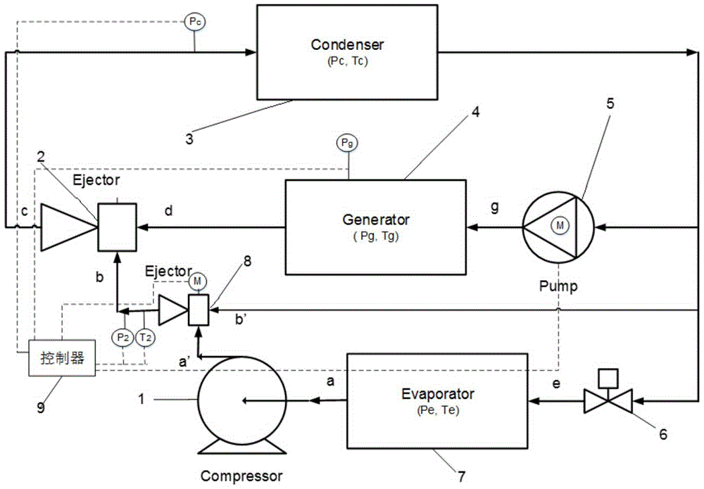
[0018] The present invention is described in detail below in conjunction with accompanying drawing:

[0019] Such as figure 1 As shown, a vapor compression-ejection coupled refrigeration system with liquid intermediate pressurization includes a condenser 3, and the output of the condenser 3 is divided into three paths, one path is connected to the input end of the pump 5, and the other path is connected to the second ejector 8 One end is connected, the third road is connected with one end of the throttle valve 6, the output end of the pump 5 is connected with the input end of the generator 4, and the output end of the generator 4 is connected with the input end of the condenser 3 through the first injector 2 , the other end of the second ejector 8 is connected to the input end of the ejector 2, and the other end of the throttle valve 6 is connected to the evaporator 7, the compressor 1 and the first ejector 2 in sequence.

[0020] The present invention proposes a liquid inter...


PUM


Abstract

The invention discloses a steam compression-ejection coupled refrigerating system with an intermediate liquid pressurization function. The steam compression-ejection coupled refrigerating system comprises a condenser. Output of the condenser is divided into three channels, the first channel is connected with an input end of a pump, the second channel is connected with one end of a second ejector, the third channel is connected with one end of a throttle valve, an output end of the pump is connected with an input end of a generator, an output end of the generator is connected with an input end of the condenser by a first ejector, the other end of the second ejector is connected with an input end of the first ejector, and the other end of the throttle valve is sequentially connected with an evaporator, a compressor and the second ejector. The steam compression-ejection coupled refrigerating system has the advantages that a branch is led out from the rear of the condenser, a branch pipeline is connected with an outlet pipeline of the compressor by the second ejector, air compressed by the compressor can be sucked and pressurized by condensed liquid, and a gas flow phase and a liquid flow phase can be formed after the air and the condensed liquid are mixed with each other and then are sucked by the first ejector; working conditions of the ejectors can be improved by a method implemented by the steam compression-ejection coupled refrigerating system, inject ratios of the ejectors can be increased, power consumed by the compressor can be saved, and the energy efficiency of the integral system can be improved.

Description

technical field [0001] The invention relates to a vapor compression-jet coupled refrigeration system. Background technique [0002] The vapor compression-jet coupled refrigeration cycle can make full use of waste heat, solar energy, low-grade heat sources, etc. to replace part of the compression work, thereby saving mechanical energy consumption and improving energy utilization efficiency. [0003] The existing vapor compression-jet coupled refrigeration cycle has disadvantages such as low efficiency, small ejector injection ratio, small ejector compression ratio, and difficulty in meeting the pressure requirements when the condensation temperature is high. Application number: 2005101110230, which proposes a "Automotive air-conditioning refrigeration system driven by compressor and tail gas waste heat mixture", which uses the waste heat of automobile exhaust gas to drive the automobile air conditioner, and the insufficient part is supplemented by the compression refrigeratio...

Claims


Application Information

Patent Timeline
Patent Type & Authority Patents(China)
IPC IPC(8): F25B25/00F25B49/00
CPCF25B25/00F25B49/00F25B2600/05
Inventor 赵红霞王雷赖艳华张科
Owner SHANDONG UNIV
Why Eureka
Try Eureka