Method for preparing porous silicon nanowire NO2 gas sensor

A gas sensor and nanowire technology, applied in the direction of material resistance, can solve the problems of high working temperature, sensitive to humid environment, affecting the stability and sensitivity of gas sensor, and achieve large porosity, high sensitivity, and improved gas sensing performance Effect

Active Publication Date: 2015-04-08
TSINGHUA UNIV
View PDF4 Cites 12 Cited by
  • Summary
  • Abstract
  • Description
  • Claims
  • Application Information

AI Technical Summary

Problems solved by technology

However, in recent years, people have found that the working temperature of tin oxide as a gas sensitive material is relatively high, and it is sensitive to humid environments, which affects its stability and sensitivity as a gas sensor.

Method used


Image

  • Method for preparing porous silicon nanowire NO2 gas sensor
  • Method for preparing porous silicon nanowire NO2 gas sensor
  • Method for preparing porous silicon nanowire NO2 gas sensor

Examples


Embodiment 1

[0025] (1) Cut the silicon wafer into a suitable shape, and carry out ultrasonic cleaning with acetone, alcohol, and deionized water in sequence, and the cleaned silicon wafer is stored in H 2 o 2 and concentrated H 2 SO 4 In a solution with a volume ratio of 1:4.

[0026] (2) Save in H 2 o 2 and concentrated H 2 SO 4 An oxide layer will be formed on the surface of the silicon wafer in the mixed solution, and 5% HF is configured to remove the oxide layer.

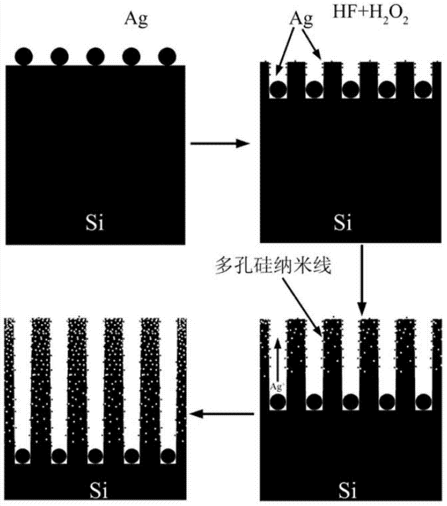
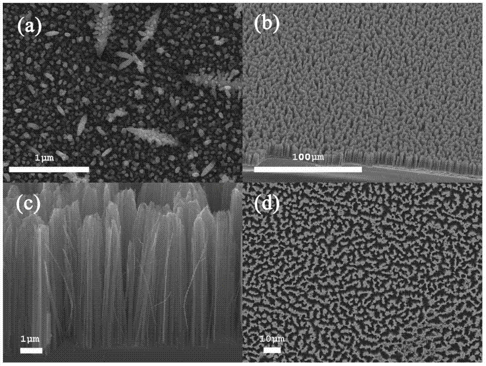
[0027] (3) Preparation of HF and AgNO 3 A mixed solution in which the concentration of HF is 4.8M, AgNO 3 Concentration of 5mM, after magnetic stirring for a certain period of time, immerse the silicon chip in it for 60s to deposit a uniform layer of Ag particles on the surface; the silicon chip after silver plating is as attached figure 2 (a) shown.

[0028] (4) Preparation of HF and H 2 o 2 The mixed solution, in which the concentration of HF is 4.8M, H 2 o 2 The concentration is 0.1M, keep warm in a consta...

Embodiment 2

[0035] (1) Cut the silicon wafer into a suitable shape, and carry out ultrasonic cleaning with acetone, alcohol, and deionized water in sequence, and the cleaned silicon wafer is stored in H 2 o 2 and concentrated H 2 SO 4 In a solution with a volume ratio of 1:4.

[0036] (2) Save in H 2 o 2 and concentrated H 2 SO 4 An oxide layer will be formed on the surface of the silicon wafer in the mixed solution, and 5% HF is configured to remove the oxide layer.

[0037] (3) Preparation of HF and AgNO 3 A mixed solution in which the concentration of HF is 3M, AgNO 3 Concentration of 8mM, after magnetic stirring for a certain period of time, immerse the silicon chip in it for 80s to deposit a uniform layer of Ag particles on the surface; the silicon chip after silver plating is as attached figure 2 (a) shown.

[0038] (4) Preparation of HF and H 2 o 2 A mixed solution in which the concentration of HF is 3M, H 2 o 2 The concentration is 1M, keep warm in a constant temper...

Embodiment 3

[0045] (1) Cut the silicon wafer into a suitable shape, and carry out ultrasonic cleaning with acetone, alcohol, and deionized water in sequence, and the cleaned silicon wafer is stored in H 2 o 2 and concentrated H 2 SO 4 In a solution with a volume ratio of 1:4.

[0046] (2) Save in H 2 o 2 and concentrated H 2 SO 4 An oxide layer will be formed on the surface of the silicon wafer in the mixed solution, and 5% HF is configured to remove the oxide layer.

[0047] (3) Preparation of HF and AgNO 3 A mixed solution in which the concentration of HF is 6M, AgNO 3 The concentration is 8mM, after a certain period of magnetic stirring, the silicon wafer is immersed in it for 50s, so that a uniform layer of Ag particles is deposited on the surface; the silicon wafer after silver plating is as attached figure 2 (a) shown.

[0048] (4) Preparation of HF and H 2 o 2 The mixed solution, in which the concentration of HF is 4.8M, H 2 o 2 The concentration is 0.5M, keep warm i...


PUM


Abstract

The invention discloses a method for preparing a porous silicon nanowire NO2 gas sensor belonging to the technical field of gas sensors. The method comprises the following steps: catalyzing chemical corrosion by utilizing metal silver, and preparing a porous silicon nanowire on the surface of a silicon chip; modifying an Ag nanoparticle layer on the surface of the porous silicon nanowire by virtue of a metal salt solution soaking or magnetron sputtering method, connecting the obtained film sample to an Ag electrode and an Ag wire, wherein the sample can serve as a gas-sensitive sensor for detecting the NO2 gas. When NO2 is introduced into a gas environment at a certain voltage, the resistance value of the sensor is obviously reduced; and after the NO2 gas is removed and air is introduced again, the resistance value of the sensor can rise again. The NO2 gas sensitive sensor prepared by the method has the characteristics of high sensitivity, low cost and high environmental stability, the resistance value of the device can be over 30 percent in the NO2 gas, and the sensor has high actual application value.

Description

technical field [0001] The invention belongs to the technical field of gas sensors, in particular to a porous silicon nanowire NO 2 Preparation method of gas sensor. Background technique [0002] There are various dangerous gases in the environment we live in, such as greenhouse effect, acid rain, ozone layer destruction and many other hazards, which have seriously threatened the survival of human beings. Therefore, it is imminent to develop a high-sensitivity, high-selectivity gas sensor to detect the content of dangerous gases in various environments and monitor their emissions. Traditional gas sensor materials are generally metal oxide systems, such as SnO 2 It is the gas sensitive material that was first put into production and is the most widely used. SnO 2 Rutile structure, N-type semiconductor, can be used to detect H 2 ,CH 4 ,NH 3 ,CO,H 2 S, propane, butane and other gases. However, in recent years, people have found that tin oxide as a gas-sensing material ...

Claims


Application Information

Patent Timeline
Patent Type & Authority Applications(China)
IPC IPC(8): G01N27/12
Inventor 李正操廖杰翠吕沙沙
Owner TSINGHUA UNIV
Why Eureka
Try Eureka