Suppression method for zero-sequence voltage caused by dual inverter switching dead area

A zero-sequence voltage, dual-inverter technology, which is applied in motor generator control, AC motor control, electronic commutation motor control, etc., can solve the problems of zero-sequence voltage in the system and affect system performance, etc.

Active Publication Date: 2015-04-08
HARBIN INST OF TECH
View PDF3 Cites 12 Cited by
  • Summary
  • Abstract
  • Description
  • Claims
  • Application Information

AI Technical Summary

Problems solved by technology

[0004] The purpose of the present invention is to solve the problem of zero-sequence voltage in the system due to the addition of dead time when the switching signals of the dual inv

Method used


Image

  • Suppression method for zero-sequence voltage caused by dual inverter switching dead area
  • Suppression method for zero-sequence voltage caused by dual inverter switching dead area
  • Suppression method for zero-sequence voltage caused by dual inverter switching dead area

Examples


specific Embodiment approach 1

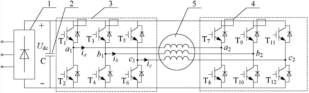
[0060] Specific implementation mode one: the following combination Figure 1 to Figure 15 Describe this embodiment, the suppression method of the zero-sequence voltage caused by the dead zone of the double inverter switch described in this embodiment, the suppression method is based on the SVPWM modulation using a combination of switches that do not generate zero-sequence voltage, the suppression method first The three-phase voltage signal of the double inverter is collected by the voltage sensor, and the three-phase voltage signal is the three-phase voltage signal after RC low-pass filtering; then the three-phase voltage signal is processed to obtain the system zero-sequence voltage; then according to The zero-sequence voltage of the system is calculated in the dead zone to obtain the compensation voltage vector, so that the zero-sequence voltage generated by the compensation voltage vector offsets the zero-sequence voltage of the system to realize the suppression of the zero-...

specific Embodiment approach 2

[0062] Specific Embodiment 2: This embodiment will further explain Embodiment 1. The method for obtaining the zero-sequence voltage of the system is: the three-phase voltage signals of the dual inverters collected by the voltage sensor are summed and calculated through an operational amplifier circuit, The calculated result is converted into a digital system zero-sequence voltage through an analog-to-digital converter.

[0063] The conversion of the summation result in this embodiment can be realized by the A / D of the DSP, and the analog quantity is converted into a digital quantity.

specific Embodiment approach 3

[0064] Specific implementation mode three: this implementation mode further explains implementation mode two, and the method for obtaining the compensation voltage vector is:

[0065] First, reverse the polarity of the zero-sequence voltage of the system to obtain the polarity of the zero-sequence voltage generated by the compensation voltage vector;

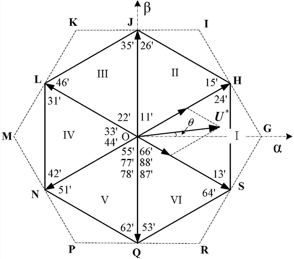
[0066] Then according to the polarity of the zero-sequence voltage generated by the compensation voltage vector and the sector where the reference voltage vector U* is located, determine the switch combination of the compensation voltage vector;

[0067] Then by increasing the conduction time of one of the two switch signals with the maximum duty cycle, the conduction time of the switch signal is increased to 2 times the dead zone time, thereby obtaining an action time of 2 times the dead zone Time-compensated voltage vector.

[0068] The zero-sequence voltage generated by the compensation voltage vector obtained in this embodi...


PUM


Abstract

The invention discloses a suppression method for zero-sequence voltage caused by a dual inverter switching dead area, belongs to the technical field of inverter control and aims to solve the problems that a system has zero-sequence voltage and system performances are affected due to addition of dead time when common direct-current bus dual inverter switching signals are switched. Based on SVPWM (space vector pulse width modulation) performed by a switch combination without zero-sequence voltage, the suppression method includes the steps: firstly, acquiring three-phase voltage signals after RC (resistance-capacitance) low-pass filter of dual inverters by a voltage sensor; processing the three-phase voltage signals to obtain system zero-sequence voltage; performing dead area compensation calculation according to the system zero-sequence voltage to obtain a compensation voltage vector, offsetting the system zero-sequence voltage by the zero-sequence voltage generated by the compensation voltage vector, and suppressing the system zero-sequence voltage. The suppression method is used for suppressing the zero-sequence voltage caused by the dual inverter switching dead area.

Description

technical field [0001] The invention relates to a method for suppressing zero-sequence voltage caused by a double-inverter switch dead zone, and belongs to the technical field of inverter control. Background technique [0002] The drive system of open-winding AC motors is powered by dual inverters, and the performance of the drive system of open-winding AC motors is improved compared to the drive system of star-connected winding AC motors with single-ended power supply. According to whether the DC buses of the dual inverters are connected in parallel, the dual inverters are divided into dual inverters with a common DC bus and dual inverters with an isolated DC bus. Among them, the buses of the common DC bus dual inverters are connected in parallel and powered by a DC power supply, which has the advantage of simple structure, but because the sum of the motor three-phase winding currents is not clamped to zero, there is a potential zero-sequence voltage in the system and zero...

Claims


Application Information

Patent Timeline
IPC IPC(8): H02M7/5387H02P21/14H02P27/12
CPCH02M7/5387H02P27/085H02M1/0038
Inventor 安群涛段建东毕恺韬孙力
Owner HARBIN INST OF TECH
Why Eureka
Try Eureka