Polling passive optical network optical layer detection method based on optical pre-coding

A passive optical network and precoding technology, applied in the direction of error detection/prevention using signal quality detectors, multiplexing system selection devices, transmission monitoring/testing/fault measurement systems, etc., can solve the monitoring time window Problems such as large range, poor correlation of PC codewords, and large insertion loss of encoders can achieve the effect of reducing fault repair time, reducing codeword coherence distance, and reducing operating costs

Inactive Publication Date: 2015-04-08
SOUTHEAST UNIV
View PDF4 Cites 11 Cited by
  • Summary
  • Abstract
  • Description
  • Claims
  • Application Information

AI Technical Summary

Problems solved by technology

However, the system has many limitations in terms of practicability: more encoder / decoder components, higher cost, larger volume, larger insertion loss of the encoder, which reduces the quality of the encoded signal; limited codeword space, and poor network scalability ;2) The PON link monitoring scheme based on periodic code PC (Optical Code), the decoder of this scheme has simple structure, low implementation cost, and small insertion loss, but the system still has some shortcomings: PC code word correlation is relatively low Poor, the reflection signal identification process is more complicated
The use of pulses of different wavelengths is only to improve the correlation characteristics of the codeword, and has not been used to further increase the encoding capacity; in addition, this scheme also decodes the summarized reflected signal, the reflected signal spectrum is complex and diverse, the decoding coherence distance is large, and the decoding process is relatively complicated
[0004] After searching, it was found that X.Zhou, X.Sun et al proposed a two-dimensional frequency hopping periodic code based on 2-DFHPC (2-D Frequency Hopping / Periodic Code ) PON link monitoring scheme, this scheme has the advantages of large code word capacity and small coherence distance, etc., but this scheme decodes the reflected signals summarized, the reflection signal spectrum is complex and diverse, and the coherence distance is still on the order of meters, and multi-user The probability of interference is relatively high, and the decoding process is relatively complicated
The above four different coding mechanism link monitoring schemes all adopt the method of randomly assigning optical codewords, and assign different optical codewords to different optical fiber branches. The monitoring time window range is large, which increases the codeword coherence distance and reduces The accuracy and efficiency of the judgment of the monitoring system

Method used


Image

  • Polling passive optical network optical layer detection method based on optical pre-coding
  • Polling passive optical network optical layer detection method based on optical pre-coding

Examples


Embodiment Construction

[0016] Below in conjunction with embodiment and accompanying drawing, technical solution of the present invention is described in detail:

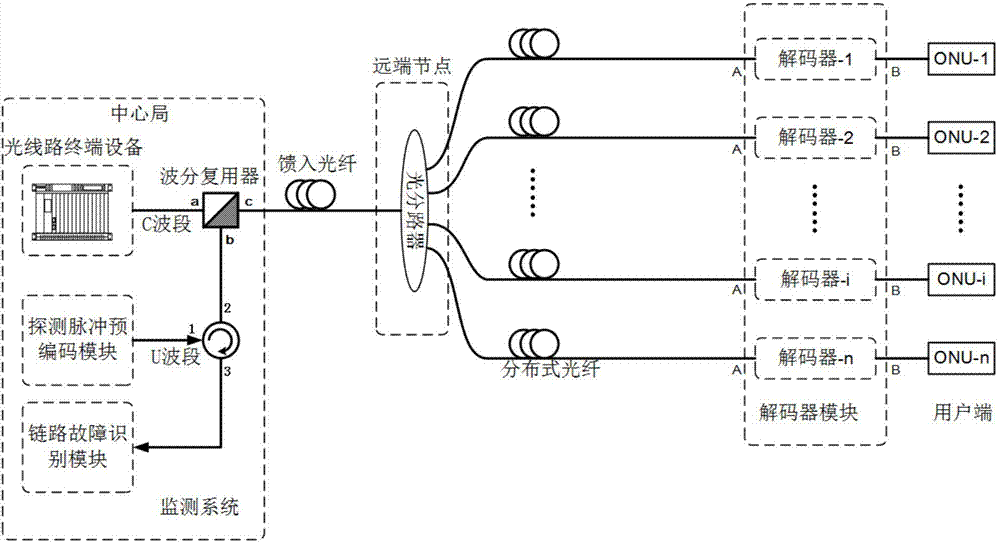
[0017] figure 1 It is a schematic diagram of a polling passive optical network optical layer detection device based on optical precoding, including a detection pulse precoding module, an optical circulator, a wavelength division multiplexer, a link fault identification module, an optical line terminal equipment, and a feed-in Optical fiber, optical splitter, distributed optical fiber, decoder module and user end, the detection pulse precoding module is connected to the first port of the optical circulator, and the link fault identification module is connected to the third interface of the optical circulator connection, the second port of the optical circulator is connected to the U-band demultiplexing port b of the wavelength division multiplexer, the C-band demultiplexing port a of the wavelength division multiplexer is connected to the ...


PUM


Abstract

The invention discloses a polling passive optical network optical layer detection device and method based on optical pre-coding. The device comprises three major modules including a detection pulse pre-coding module, a link fault recognition module and a decoder module, wherein the detection pulse pre-coding module and the link fault recognition module are connected with an OLT (optical line terminal) device and a feed-in optical fiber through an optical circulator and a wavelength division multiplexer, and the feed-in optical fiber is connected with each distributive optical fiber through an optical branching device positioned at a remote end node, and is connected with each user end through different decoders at the tail end of each distributive optical fiber. The device and the method have the advantages that pre-coding detection pulse signals are used, a polling mode is adopted, and the fault monitoring only aims at the optical fiber link of one target user in one time. The length of the monitored branch link is known, a detection time window is reduced to a very small time window, the code word coherent distance is reduced, and the accuracy of a monitoring system is improved.

Description

technical field [0001] The invention belongs to the technical field of optical fiber communication and relates to a polling type passive optical network optical layer detection method based on optical precoding. Background technique [0002] In recent years, the passive optical network PON (Passive Optical Network) technology in the field of optical access has been widely used. The continuous development of passive optical network PON technology not only improves the data transmission rate, but also increases the number of bearer users. Therefore, any failure (breakage, aging or bending loss) of any optical link (feeder fiber and distribution fiber) in the PON network will lead to the loss of a large amount of data information, reduce user satisfaction, and bring economic losses to network operators. Therefore, PON link fault detection methods have received increasing attention in the past few years. The traditional optical time domain reflectometer OTDR (Optical Time Doma...

Claims


Application Information

Patent Timeline
Patent Type & Authority Applications(China)
IPC IPC(8): H04Q11/00H04B10/07H04L1/00H04L1/20
Inventor 朱敏张教张旋王东鹏孙小菡
Owner SOUTHEAST UNIV
Why Eureka
Try Eureka