A method of manufacturing a semiconductor device

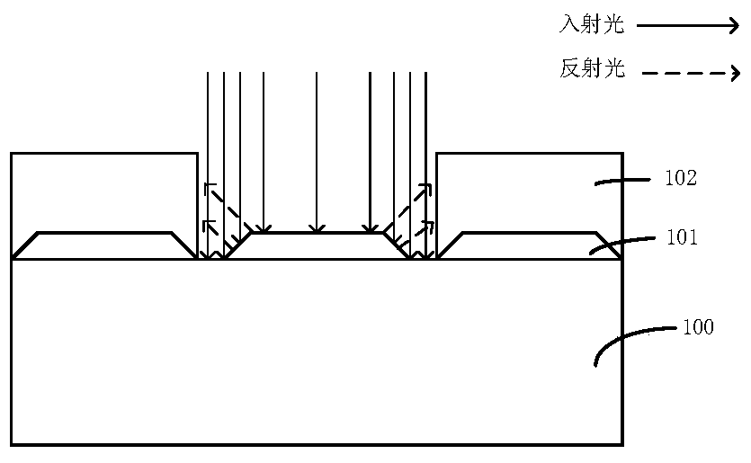
A semiconductor and device technology, applied in the field of implantlithography (Implantlithography) technology, can solve problems such as complex use, limited performance, and pre-layer film damage, and achieve the effects of avoiding damage, solving reflection, and improving performance

Active Publication Date: 2018-07-20
SEMICON MFG INT (SHANGHAI) CORP
View PDF4 Cites 0 Cited by
  • Summary
  • Abstract
  • Description
  • Claims
  • Application Information

AI Technical Summary

Problems solved by technology

However, TARC and DBARC have limited performance
The use of OPC bias rules is very complicated, which increases the complexity of the process
It is also proposed to use the traditional BARC process in the implant lithography process. However, the damage problem of the pre-layer film will be generated in the etching step. Therefore, the traditional BARC process cannot be applied to the implant layer (Implant layer)

Method used


Image

  • A method of manufacturing a semiconductor device
  • A method of manufacturing a semiconductor device
  • A method of manufacturing a semiconductor device

Examples


Embodiment Construction

[0020] In the following description, numerous specific details are given in order to provide a more thorough understanding of the present invention. It will be apparent, however, to one skilled in the art that the present invention may be practiced without one or more of these details. In other examples, some technical features known in the art are not described in order to avoid confusion with the present invention.

[0021] For a thorough understanding of the present invention, a detailed description will be set forth in the following description to illustrate the method of the present invention. Obviously, the practice of the invention is not limited to specific details familiar to those skilled in the semiconductor arts. Preferred embodiments of the present invention are described in detail below, however, the present invention may have other embodiments besides these detailed descriptions.

[0022] It should be noted that the terms used herein are for the purpose of des...


PUM

PropertyMeasurementUnit
thicknessaaaaaaaaaa
thicknessaaaaaaaaaa
thicknessaaaaaaaaaa

Abstract

The invention relates to a method for manufacturing a semiconductor device. The method comprises the following steps: providing a semiconductor substrate; forming a front layer on the semiconductor substrate; successively forming a thin oxide layer and a high-etching-rate bottom antireflective coating on the front layer; forming a patterned photoresist layer on the high-etching-rate bottom antireflective coating; according to the patterned photoresist layer, etching the high-etching-rate bottom antireflective coating so as to form an opening exposing the thin oxide layer; removing the patterned photoresist layer; and removing the exposed thin oxide layer. According to the invention, in the manufacture process of the semiconductor device, the high-etching-rate bottom antireflective coating and the thin oxide layer are formed on the substrate, such that the problem of reflection of the substrate when an injection photoetching process is carried out is solved, the problem of damage caused to the front layer and the substrate is avoided, and the performance of the device is improved.

Description

technical field [0001] The present invention relates to a semiconductor manufacturing process, in particular, the present invention relates to an implantlithography (Implantlithography) process. Background technique [0002] Integrated circuits (ICs) have grown from a handful of interconnected devices fabricated on a single silicon chip to millions of devices. Current ICs offer performance and complexity far beyond what was originally imagined. To achieve improvements in complexity and circuit density (i.e., the number of devices that can be packed into a given chip area), the size of the smallest device feature, also known as device "geometry," has become smaller with each IC generation. Small. Semiconductor devices are now fabricated with features that span less than a quarter of a micron. [0003] With the continuous development of semiconductor technology, the improvement of integrated circuit performance is mainly achieved by continuously shrinking the size of integr...

Claims


Application Information

Patent Timeline
Patent Type & Authority Patents(China)
IPC IPC(8): H01L21/32H01L21/027
CPCH01L21/0276
Inventor 舒强郝静安
Owner SEMICON MFG INT (SHANGHAI) CORP
Why Eureka
Try Eureka