Cooled stationary anode for an x-ray tube

A technology of X-ray tube and anode, which is applied in the direction of X-ray tube cooling, X-ray tube anode cooling, X-ray tube cooling method, etc., to achieve the effects of enhanced cooling, good cooling, and technical problem solving

Inactive Publication Date: 2015-04-15
QUANTUM TECH DEUT
View PDF6 Cites 5 Cited by
  • Summary
  • Abstract
  • Description
  • Claims
  • Application Information

AI Technical Summary

Problems solved by technology

Unfortunately, the high kinetic energy of the electrons incident on the anode is converted not only into short-wavelength radiation, but also into heat

Method used


Image

  • Cooled stationary anode for an x-ray tube

Examples


Embodiment Construction

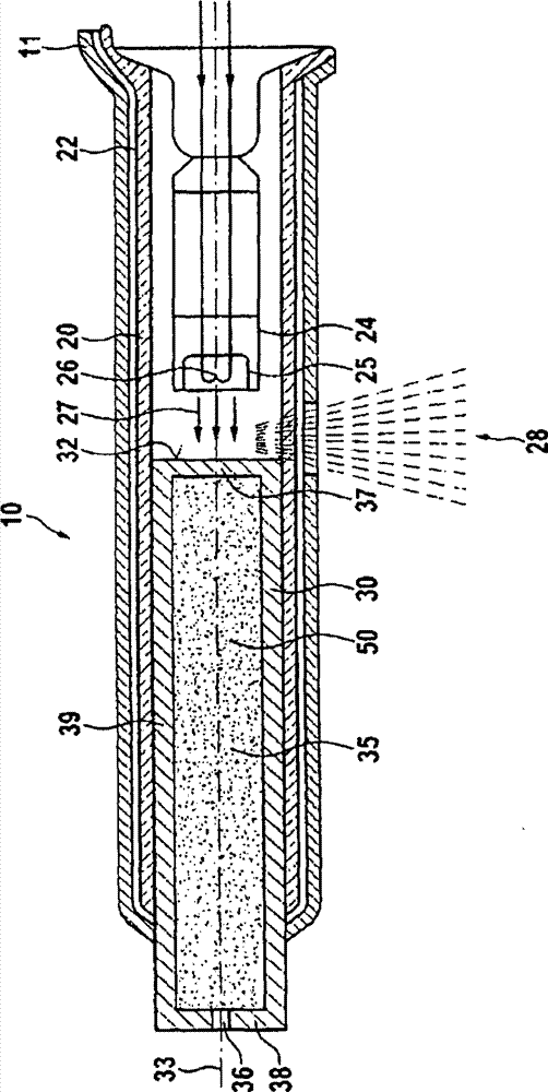
[0022] figure 1 The X-ray tube 10 in has a chamber 20, which consists of a chamber wall, eg glass. This chamber 20 is enclosed in a shell 11 , for example made of some metal. Between the chamber wall 20 and the shell 11 there is a space 22 in which the coolant circulates. Preferably, coolant circulates between space 22 and a heat exchanger (not shown).

[0023] The chamber 20 is evacuated and encloses a cathode assembly 24 having a wire cathode 26 connected to a power source. By energizing the cathode 26, the cathode 26 can be heated resulting in thermal emission of electrons.

[0024] Chamber 20 also surrounds a portion of anode 30 . The anode 30 resembles a cylindrical rod with a cylindrical axis 33 . Anode 30 has a front side facing cathode assembly 24 . On the front side of the disk 34 there is a peripheral target area 32 for the electrons 27 emitted by the cathode 26 and subsequently accelerated by the voltage between the cathode 26 and the anode 30 . The target ar...


PUM


Abstract

An X-ray tube 10 with an anode 30 comprising at least a rod shaped body with a front wall having target area 32 as target for an electron beam 27 on its frontal side provides a high intensity of X-ray radiation if the anode 30 has at least one cavity extending to the front wall, the cavity having a coating 50 of at least one inorganic salt.

Description

technical field [0001] The invention relates to a stationary anode for cooling of an X-ray tube and to an X-ray tube. Background technique [0002] X-ray tubes are of considerable importance in medical imaging, especially as X-ray sources for CT-scanners. Of course, X-ray tubes are equally important in other technical fields such as, to name a few, the determination of crystal structures (see, for example, Ashcroft Mermin's Solid State Physics, Sanders University Press, Chapter 6 ), or fast and reliable radiography which is already commonly used by Customs. These applications require high radiation powers to obtain detailed information about objects that need to undergo X-ray based analysis. [0003] Briefly, X-rays are produced by the sharp deceleration of pre-accelerated electrons. For this purpose, the X-ray tube includes a cathode, usually in the form of a helical wire. By applying an electric current to the filament, the filament is heated to induce thermal emission...

Claims


Application Information

Patent Timeline
Patent Type & Authority Applications(China)
IPC IPC(8): H01J35/12
CPCH01J35/06H01J2235/1291H01J2235/1204H01J2235/1262H01J35/12H01J2235/1266H01J2235/1225H01J35/064H01J35/13H01J2235/1287
Inventor K·陈
Owner QUANTUM TECH DEUT
Why Eureka
Try Eureka