Self-anchored suspension bridge with fish spine structure

A self-anchored suspension bridge and fish-back beam technology, applied in suspension bridges, bridge forms, bridges, etc., can solve the problems of complex local stress in the anchoring area, large volume of main cables and suspender anchoring beams, and limited spans, etc., and achieve multi-modeling. Design imagination space, diversify landscape design, reduce the effect of height control

Active Publication Date: 2016-03-30
SHANGHAI URBAN CONSTR DESIGN RES INST GRP CO LTD
View PDF5 Cites 0 Cited by
  • Summary
  • Abstract
  • Description
  • Claims
  • Application Information

AI Technical Summary

Problems solved by technology

[0013] 1) if figure 1 As shown, since the main cable 20 is directly anchored to the end of the stiffened beam 10, the beam bears a huge axial force. Therefore, it is necessary to increase the cross section of the beam, thereby limiting the span, and when the span increases to a certain extent, the project cost will be greatly reduced. Increase
[0014] 2) The construction steps are limited. The traditional self-anchored suspension bridge must hoist the main cable 20 and install the boom 40 after the stiffening beam 10 and bridge tower 30 are completed, so a large number of temporary supports need to be built to install the stiffening beam 10
Therefore, if the span of the self-anchored suspension bridge increases, the additional construction cost will increase.
[0015] 3) The local stress in the anchorage area is complex
The main cable and suspender anchor beams have a large volume, which often becomes a difficulty in landscape design
[0016] 4) Due to the large deformation of the structural system during the construction process, the main cable has an obvious nonlinear effect, which makes the construction control more complicated when the suspender is 40 tensioned

Method used


Image

  • Self-anchored suspension bridge with fish spine structure
  • Self-anchored suspension bridge with fish spine structure
  • Self-anchored suspension bridge with fish spine structure

Examples


Embodiment 1

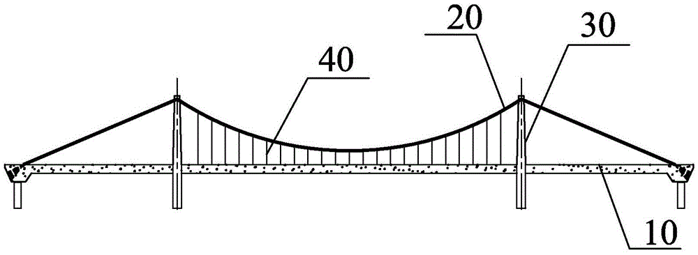
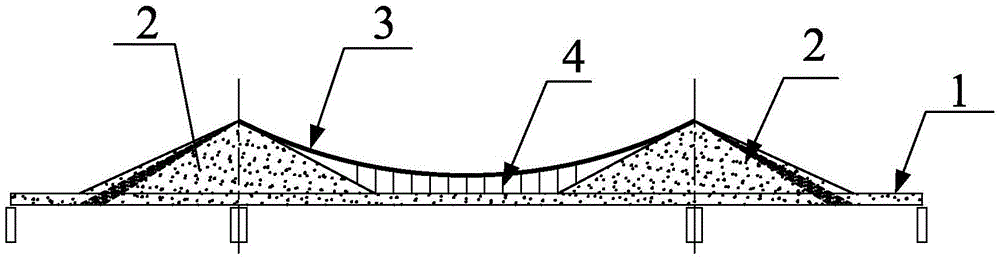
[0063] The purpose of the present invention is achieved through the following technical solutions: as figure 2 As shown, the self-anchored suspension bridge of the fish spine structure provided by the present embodiment is a self-anchored suspension bridge with a double span three-span fish spine structure, which includes: a main beam of a fish spine structure, several main cables 3, and the main cables 3 The girder comprises: a full-length box-type deck 1 of equal height, and several variable-height fish ridge walls 2 erected on the same-height box-type deck, and several tensioned ridges arranged between the main cables 3 and The suspenders 4 between the equal-height box-type bridge decks 1, the equal-height box-type bridge deck 1 and the fish ridge wall 2 are formed by concrete pouring, and the two ends of each main cable 3 are anchored on two adjacent fish bridges. Inside the fish ridge of ridge wall 2. By means of several variable-height fish-ridge walls erected on the s...

Embodiment 2

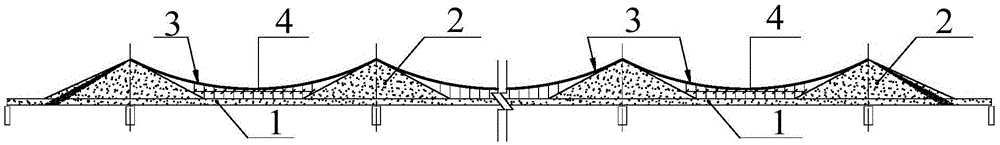
[0080] On the facade, the span diameter, number of spans, number of main cables, and number of suspenders are not limited according to actual engineering and force requirements. Therefore, the present embodiment provides a self-anchored suspension bridge with multi-tower and multi-span fish-back structure.

[0081] image 3 The elevation direction structure diagram of the self-anchored suspension bridge with multi-tower span fish-back structure.

[0082] Such as image 3 As shown, the number of main cables 3 of the self-anchored suspension bridge in this embodiment is multiple, and the number of spans of the self-anchored suspension bridge is multiple.

[0083] The structures of the fish ridge wall 2 , the main cable 3 , and the contoured box bridge deck 1 in this embodiment, as well as the connection methods between the suspender 4 and the main cable 3 , and the fish ridge wall 2 are all identical to those in Embodiment 1.

Embodiment 3

[0085] According to the needs of actual engineering and stress, the fish ridge wall of the self-anchored suspension bridge in this embodiment is a single fish ridge wall.

[0086] Figure 4a It is the layout structure diagram of the monolithic fish ridge wall and bridge tower in the direction of cross section. Such as Figure 4a As shown, the single-piece fishback wall is arranged in the middle of the cross-section of the equal-height box-type bridge deck 1 .

[0087] The structures of the fish ridge wall 2 , the main cable 3 , and the contoured box bridge deck 1 in this embodiment, as well as the connection methods between the suspender 4 and the main cable 3 , and the fish ridge wall 2 are all identical to those in Embodiment 1.


PUM


Abstract

The invention discloses a self-anchorage type suspension bridge of a fish bone beam structure. The self-anchorage type suspension bridge of the fish bone beam structure comprises a main beam and main cables, wherein the two ends of the main cables and the main beam are anchored, and the main beam of the self-anchorage type suspension bridge is of a fish bone beam structure. The main beam comprises an equal-altitude box type bridge panel used for bearing a horizontal component of the main cables to generate axial pressure and internal bending force, and a plurality of height-variable fish bone walls erected on the equal-altitude box type bridge panel and enabling the bending moment bearing position of the main beam to be stressed and in a reverse T shape. The two ends of each main cable are anchored in the two adjacent fish bone walls, and a set of suspenders used for tensioning are arranged in the area between each main cable and the main beam. The cross section of the main beam is composed of the two parts of the equal-altitude box type bridge panel and the height-variable fish bone walls, the design control height of the longitudinal section is controlled by the equal-altitude box type bridge panel, the bending moment bearing position is reasonably stressed and in a reverse T shape, the fish bone walls can be heightened according to stress requirements, and the design control height of the longitudinal section is not increased. Thus, the self-anchorage type suspension bridge of the fish bone beam structure is favorable for overall arrangement of a project.

Description

technical field [0001] The invention relates to a suspension bridge, in particular to a self-anchored suspension bridge with a fish spine structure. Background technique [0002] Such as figure 1 As shown, the self-anchored suspension bridge is an ancient bridge type. The difference between it and the conventional ground-anchored suspension bridge is that there is no ground anchor, and the stiffened girder bears the horizontal force of the main cable, resulting in a large axial pressure on the main girder. Its main cable 20 is directly anchored at the beam end of the stiffened beam 10, and the main beam directly bears the horizontal tension in the main cable 20 without the need for a huge anchorage, which provides a way to build a suspension bridge where it is inconvenient to build an anchorage. Solution. [0003] The superstructure of the self-anchored suspension bridge comprises four parts: a stiffening beam 10 (usually also called a main beam), a main cable 20, a suspen...

Claims


Application Information

Patent Timeline
Patent Type & Authority Patents(China)
IPC IPC(8): E01D11/02E01D19/00
CPCE01D11/02E01D19/00E01D2101/24
Inventor 陆元春傅梅赵成栋
Owner SHANGHAI URBAN CONSTR DESIGN RES INST GRP CO LTD
Why Eureka
Try Eureka