
Engine intake and exhaust system and vehicle

An engine, intake and exhaust technology, used in engine components, combustion engines, machines/engines, etc., can solve problems such as harmful gases and particulate matter.

Active Publication Date: 2017-10-20
GREAT WALL MOTOR CO LTD
View PDF8 Cites 0 Cited by
  • Summary
  • Abstract
  • Description
  • Claims
  • Application Information

AI Technical Summary

Problems solved by technology

[0004] In view of this, the present invention aims to propose an engine intake and exhaust system to solve the technical problem that the fuel produces harmful gases and more particulate matter during the combustion process when the vehicle is under low or medium load.

Method used


Image

  • Engine intake and exhaust system and vehicle
  • Engine intake and exhaust system and vehicle

Examples


Embodiment 1

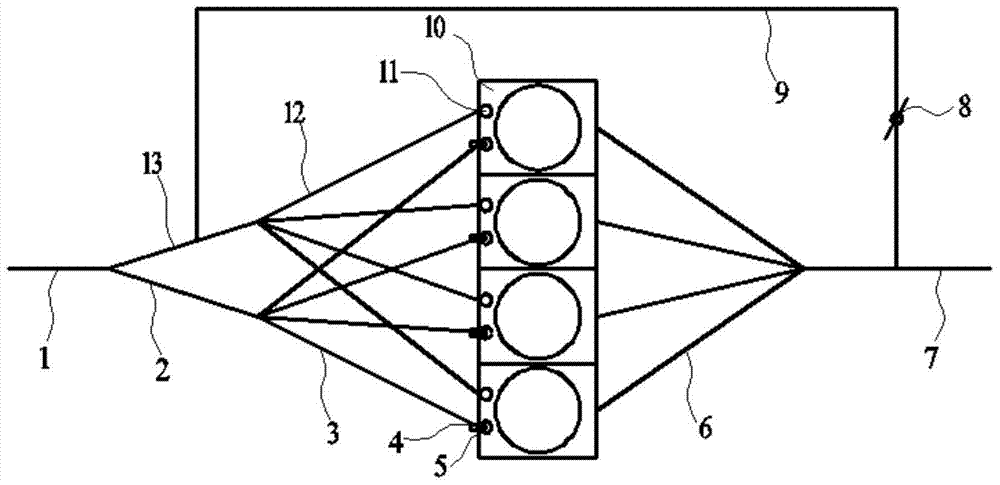
[0030] Taking a four-cylinder dual-fuel engine as an example, such as figure 1 shown. This type of fuel engine is an engine that injects gasoline premixed into the port and injects diesel fuel into the cylinder to ignite.

[0031] An embodiment of the present invention is an engine intake and exhaust system, such as figure 1 Shown, comprise cylinder (four), and cylinder is provided with tangential air passage 5 and spiral air passage 11; Tangential air passage 5 connects first intake manifold 3, and first intake manifold 3 (four) common Connect the first intake pipe 2; the spiral air channel 11 connects the second intake manifold 12, and the second intake manifold 12 (four) connects the second intake pipe 13; the second intake pipe 13 is connected with the exhaust manifold of the engine 7 is connected with an EGR pipeline 9 of the exhaust gas recirculation system, and an EGR valve 8 is arranged on the EGR pipeline 9 .

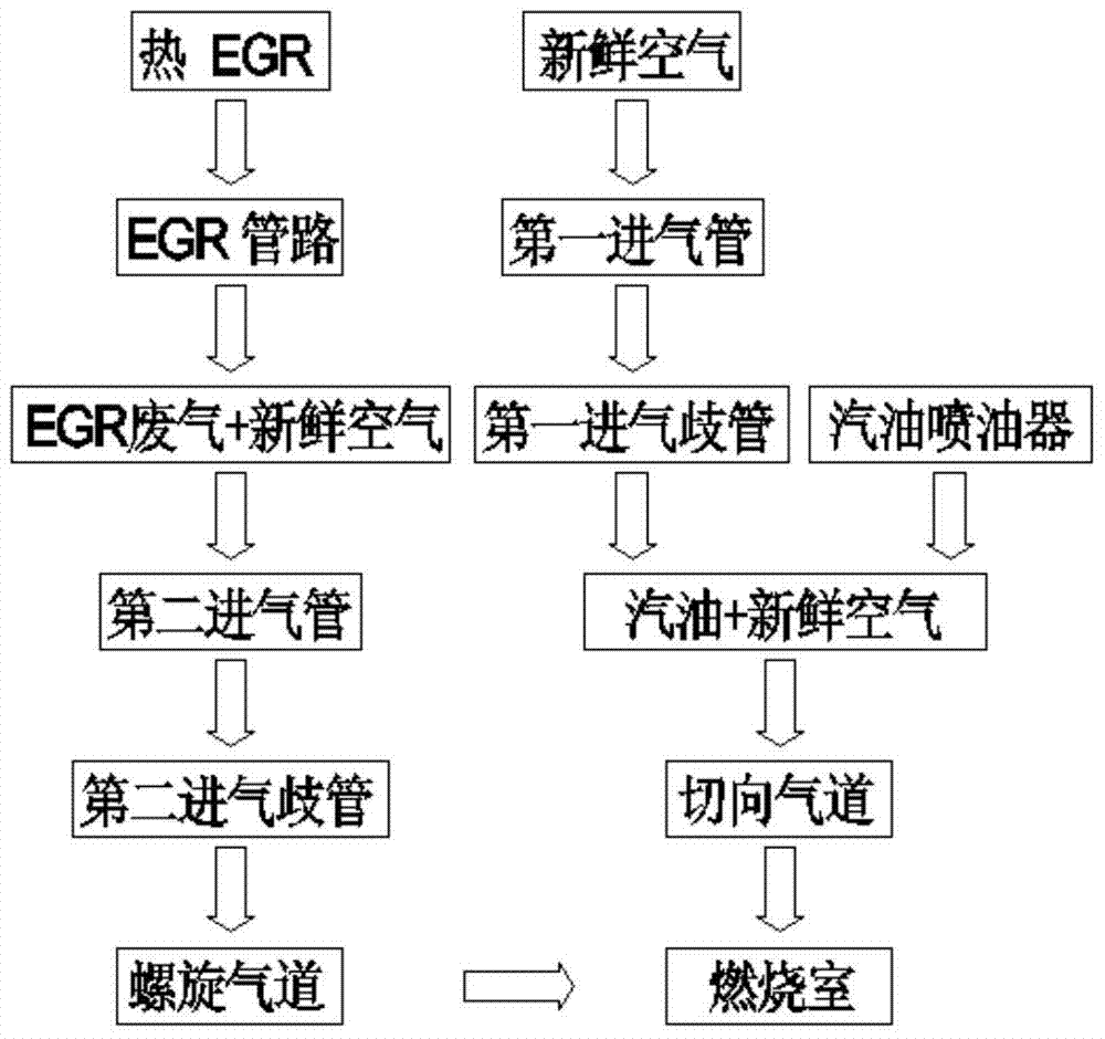
[0032] Such as figure 1 and figure 2 As shown, the ...

Embodiment 2

[0044] The embodiment of the present invention is a vehicle provided with the engine intake and exhaust system in the first embodiment above.

[0045] Compared with the prior art, the vehicle in this embodiment has the same advantages as the engine intake and exhaust system in the first embodiment above, that is, it can effectively reduce the emission of harmful gases such as HC, CO and NOx, and particulate matter , and its specific working principle will not be repeated here.


PUM


Abstract

The invention provides an engine inlet and exhaust system. The engine inlet and exhaust system comprises an air cylinder, and the air cylinder is provided with a tangential air way and a spiral air way; the tangential air way is connected with a first inlet manifold, and the first inlet manifold is connected with a first inlet pipe; the spiral air way is connected with a second inlet manifold, and the second inlet manifold is connected with a second inlet pipe; and a waste gas recirculation system EGR pipeline is connected between the second inlet pipe and an exhaust manifold of an engine, and an EGR valve is arranged on the EGR pipeline. The waste gas quantity of the EGR pipeline is controlled through the EGR valve, and the aim that EGR waste gas and oil-gas mixed gas are distributed in an area-divided manner is achieved, so that the emission load of HC and the emission load of CO of the engine are reduced.

Description

technical field [0001] The invention relates to the technical field of vehicle engines, in particular to an engine intake and exhaust system. Background technique [0002] The engine of existing automobile generally adopts the engine of internal combustion engine, and this is to have utilized the characteristic that internal combustion engine has high thermal efficiency, and its main fuel is petroleum (gasoline and / or diesel oil). [0003] The gas exhausted by the engine generally contains various harmful components such as unburned hydrocarbons (HC), carbon monoxide (CO), aldehyde compounds, nitrogen oxides (NOx) and particulate matter (Soot); HC and NOx are exposed to sunlight It will cause photochemical reactions, form photochemical smog, irritate the eyes and throat, and hinder plant growth; the particulate matter (PM) emitted by the engine is generally less than 1 micron, which can be inhaled into the bottom of human lungs, threatening human health. When the vehicle is...

Claims


Application Information

Patent Timeline
IPC IPC(8): F01N13/00F02M35/104
CPCY02T10/12
Inventor 赵中芹王超史晓刚刘晓娜
Owner GREAT WALL MOTOR CO LTD
Learn More