Organic light emitting diode
A light-emitting diode, organic technology, applied in the field of electronics, can solve the problems of large emission spectrum changes, weak fluorescent blue light, and unstable spectrum, and achieve the effects of improving luminous efficiency, good spectral stability, and improving stability
- Summary
- Abstract
- Description
- Claims
- Application Information
AI Technical Summary
Problems solved by technology
Method used
Image
Examples
preparation example Construction
[0064] The preparation method of the organic light-emitting diode of the present invention is specifically prepared according to the following method:
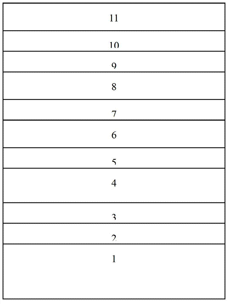
[0065] First photoetch the ITO layer 2 on the ITO glass into a thin strip electrode, then clean it, dry it with nitrogen, bake it in a vacuum oven at 120°C for 0.5~1h, treat it with oxygen plasma for 1~5min, and then transfer it In the vacuum coating system, wait until the vacuum degree reaches 1~5×10 -4 At Pa, on the ITO layer 2, a hole interface layer 3, a hole transport layer 4, an electron / exciton blocking layer 5, a red phosphorescent dye-doped light-emitting layer 6, a spacer layer 7, and a green phosphorescent dye doped Miscellaneous light-emitting layer 8, electron transport / hole blocking layer 9, electron interface layer 10 and cathode 11, where the two electrodes cross each other to form the light-emitting area of the device, and the area of the light-emitting area is 16mm 2 , the hole interface layer 3 has a thic...
Embodiment 1
[0069] First, the ITO anode 2 on the glass substrate 1 is photolithographically formed into an electrode with a width of 4 mm and a length of 30 mm, then cleaned, blown dry with nitrogen, placed the glass in a vacuum oven and baked at 120°C for 30 minutes, then sprayed with oxygen plasma After processing for 2 minutes, put the glass into the vacuum coating system. When the vacuum degree of the vacuum coating system reaches 1~5×10 -4 Pa, sequentially vapor-deposit MoO on the ITO anode 2 3 Hole interface layer 3, NPB hole transport layer 4, TAPC electron / exciton blocking layer 5, red phosphorescent dye Ir (MDQ) 2(acac) Emitting layer 6 doped with hole transport material TCTA, hole transport material TCTA and electron transport material Be(PP) 2 Mixed spacer layer 7, green phosphorescent dye (ppy) 2 Ir (acac) Doped electron transport material Be(PP) 2 The light-emitting layer 8, Be (PP) 2 The electron transport / hole blocking layer 9, the electron interface layer 10 of LiF a...
Embodiment 2
[0072] The preparation method is the same as that of Example 1, the difference is: (ppy) 2 Ir (acac) In Be (PP) 2 The doping concentration in is controlled at 0.3wt%.
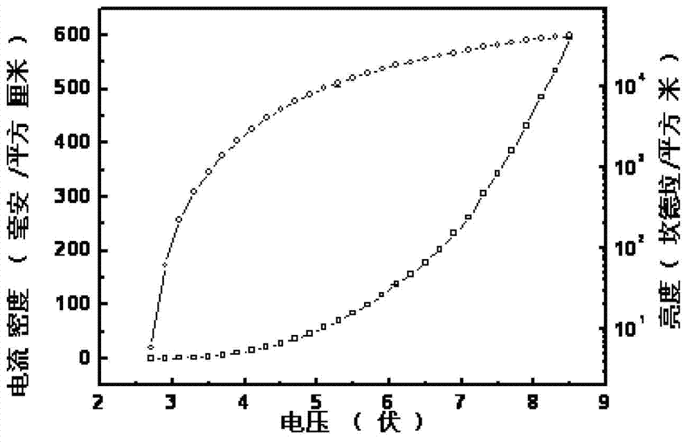
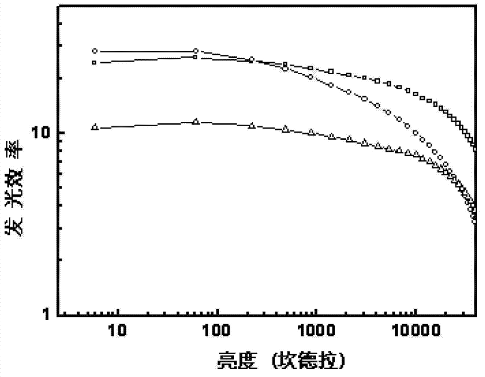
[0073] Figure 5 The current density-brightness-voltage characteristic curve of the fluorescent / phosphorescent hybrid white light organic light-emitting diode prepared for Example 2, the ○ curve in the figure is the brightness-voltage curve of the organic light-emitting diode, and the □ curve is the current density-voltage of the organic light-emitting diode curve, by Figure 5 It can be seen that the lighting voltage of the device is 2.6 volts, and the maximum brightness of the device exceeds 50000cd / m 2 , the brightness at 3.3V voltage is 1000cd / m 2 . Figure 6 is the brightness-power efficiency-current efficiency-quantum efficiency characteristic curve of the device, the □ curve in the figure is the current efficiency curve of the diode, ○ is the power efficiency curve of the diode, and the △ curve is ...
PUM
| Property | Measurement | Unit |
|---|---|---|
| band gap | aaaaa | aaaaa |
| band gap | aaaaa | aaaaa |
| thickness | aaaaa | aaaaa |
Abstract
Description
Claims
Application Information
 - R&D
- Intellectual Property
- Life Sciences
- Materials
- Tech Scout
- Unparalleled Data Quality
- Higher Quality Content
- 60% Fewer Hallucinations
Browse by: Latest US Patents, China's latest patents, Technical Efficacy Thesaurus, Application Domain, Technology Topic, Popular Technical Reports.
© 2025 PatSnap. All rights reserved.Legal|Privacy policy|Modern Slavery Act Transparency Statement|Sitemap|About US| Contact US: help@patsnap.com


