Servo control variable piston pump and control method thereof

A servo control, variable plunger technology, applied in the direction of variable displacement pump components, pumps, multi-cylinder pumps, etc., can solve the problems of difficult control, inability to meet, poor static characteristics, etc., to achieve good system response characteristics and reduce operation. Difficulty and easy operation

Inactive Publication Date: 2015-04-22
南京萨伯工业设计研究院有限公司
View PDF6 Cites 2 Cited by
  • Summary
  • Abstract
  • Description
  • Claims
  • Application Information

AI Technical Summary

Problems solved by technology

The current constant-pressure variable pump is not only complex in system, but also difficult to control; at the same time, the variable cylinder maintains relatively poor static characteristics without external manipulation, so that the hydraulic pump cannot stop pumping oil in time and is in a zero position; while the variable cylinder The internal components need to be lubricated after long-term operation to maintain normal operation. If the lubrication function is added to the existing plunger pump, the production cost will increase, and the load on the hydraulic pump will also be increased, and because the hydraulic pump converts mechanical energy For hydraulic energy, the pump body is prone to overload during operation, and how to improve safety performance is also a problem that cannot be ignored; the existing plunger pumps have low integration and poor flexible application characteristics in the system, which cannot meet the needs of modern highly integrated systems.

Method used


Image

  • Servo control variable piston pump and control method thereof
  • Servo control variable piston pump and control method thereof
  • Servo control variable piston pump and control method thereof

Examples


Embodiment Construction

[0029] In order to make the technical means, creative features, goals and effects achieved by the present invention easy to understand, the present invention will be further described below in conjunction with specific illustrations.

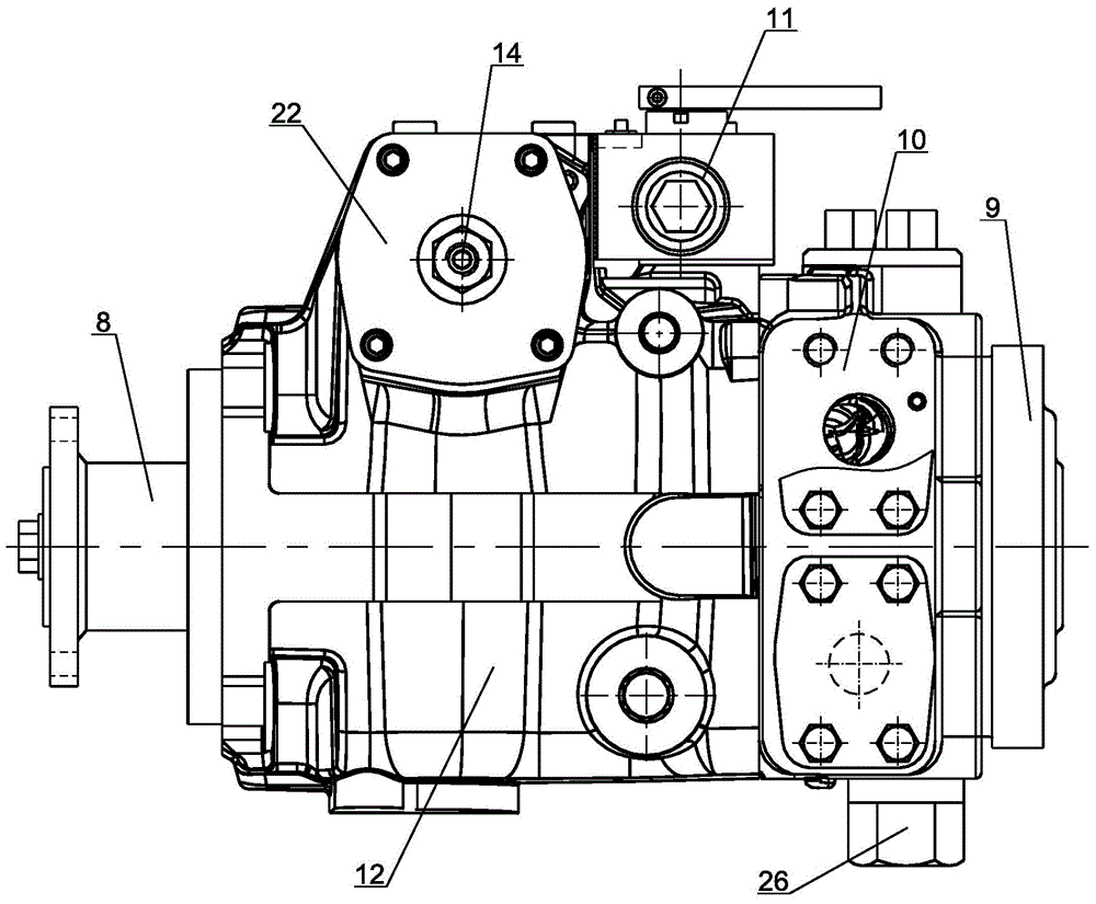
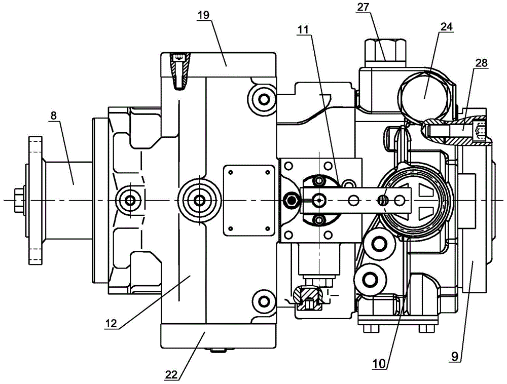
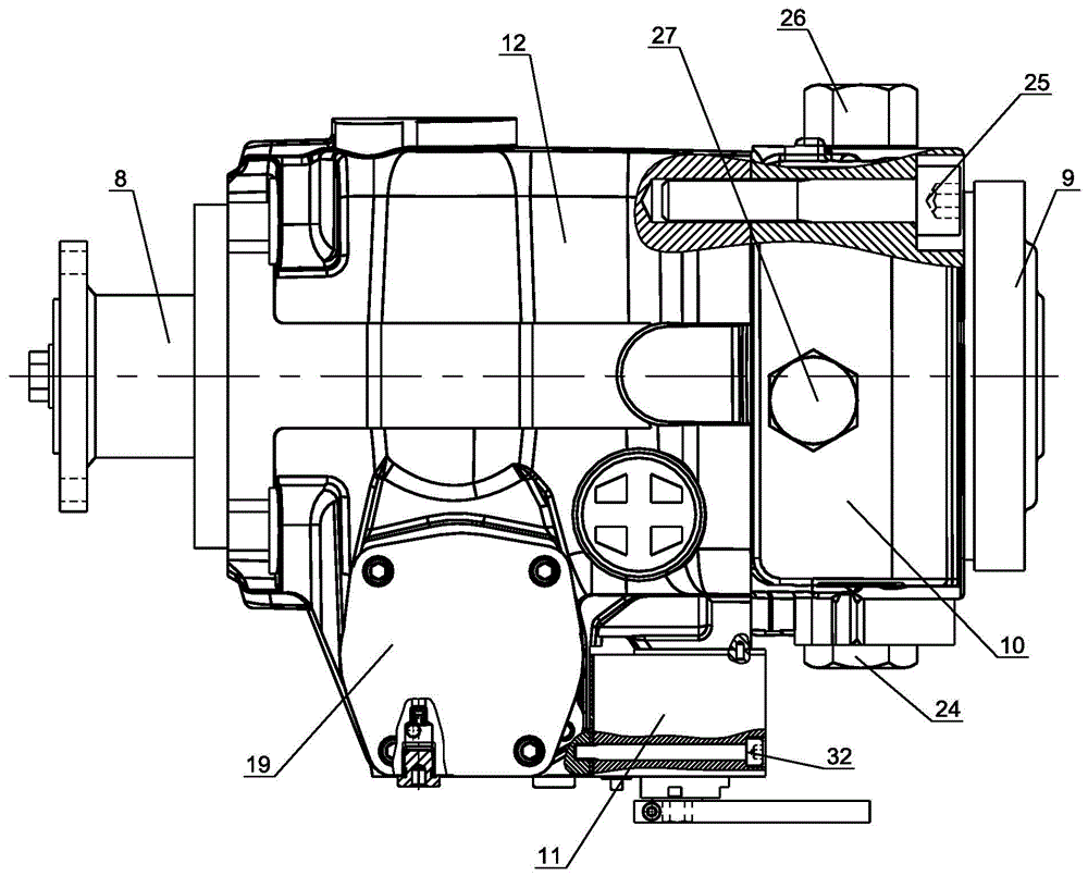
[0030] see Figure 1 to Figure 6 Servo-controlled variable plunger pump, including skeleton oil seal 1, bottom crescent bearing 2, swash plate 3, pressure plate 4, plunger assembly 5, cylinder block 6, oil distribution plate 7, transmission flange 8, charge pump 9, valve Body 10, servo control valve 11, housing 12, variable cylinder 13, central shaft 14, slider 15, top crescent bearing 16, ball bearing 17, driving shaft 18, left end cover 19, main return spring 20, auxiliary return spring 21. Right end cover 22, spring seat 23, bottom high pressure relief valve 24, valve body fastening bolts 25, top high pressure relief valve 26, low pressure relief valve 27, charge pump fastening bolts 28, spring cover 29, servo feedback Rod 30 , servo valve v...


PUM


Abstract

A servo control variable piston pump comprises a shell. A valve body is installed at the lower end of the shell. An oil supplementary pump is installed on the valve body in a fastened mode. A transmission flange is installed at the upper end of a driving shaft. The middle of the driving shaft is installed inside the shell through a ball bearing in a supported mode. The lower end of the driving shaft is installed inside a sliding bearing. The sliding bearing is installed inside the valve body. A bottom crescent bearing and a top crescent bearing for installation of a swash plate are arranged on the shell. A piston assembly is pressed on the swash plate through a pressure plate. An oil distribution disc is installed on the valve body. A cylinder body is pressed on the oil distribution disc. A variable cylinder body is installed inside the shell. A center shaft penetrates through the variable cylinder body. A reset assembly is arranged at the right end of an inner cavity of the variable cylinder body. A sliding block is arranged on one side of the reset assembly so that the swash plate can be prevented from being inclined. A servo control valve is installed on the shell. The displacement can be changed in real time by controlling the servo control valve, so that the operating difficulty is effectively lowered, and the various system requirements are met; in addition, a safety control device is further arranged on the valve body and used for overload protection during oil pumping.

Description

technical field [0001] The invention relates to the technical field of plunger pump control, in particular to a servo-controlled variable plunger pump and a control method thereof. Background technique [0002] As the most critical power component of the hydraulic system, the performance of the hydraulic pump directly affects the characteristics of the entire hydraulic system. The current constant pressure variable pump is not only complex in system, but also difficult to control; at the same time, the variable cylinder maintains relatively poor static characteristics without external manipulation, so that the hydraulic pump cannot stop pumping oil in time and is in a zero position; while the variable cylinder The internal components need to be lubricated after running for a long time to maintain normal operation. If the lubrication function is added to the existing plunger pump, the production cost will increase, and the load on the hydraulic pump will also be increased, an...

Claims


Application Information

Patent Timeline
Patent Type & Authority Applications(China)
IPC IPC(8): F04B1/12F04B1/26F04B53/18
Inventor 张祝陈力航沈陆明
Owner 南京萨伯工业设计研究院有限公司
Why Eureka
Try Eureka