Ultralow-dust rear smoke channel system of boiler
A tail flue, ultra-low ash technology, applied in combustion methods, lighting and heating equipment, exhaust gas devices, etc., can solve problems such as performance degradation, affecting the normal operation of the boiler, reliability and economic impact, and avoid poisoning , Improve economy and reliability, and improve efficiency
- Summary
- Abstract
- Description
- Claims
- Application Information
AI Technical Summary
Problems solved by technology
Method used
Image

Examples
Embodiment 1
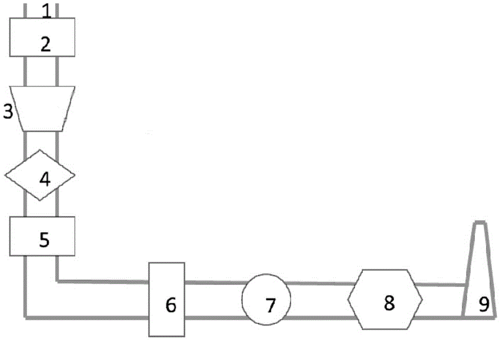
[0026] figure 2 Shown is a specific embodiment of the present invention, which also uses a 125MW coal-fired boiler. The boiler uses a high-temperature dust removal system 3 arranged before the denitrification system 4 to replace the traditional electrostatic precipitator 11. The boiler furnace (not shown) discharges The dust-laden flue gas enters the economizer 2 through the flue inlet 1, and then enters the denitrification system 4, the air preheater 5, the flue gas waste heat recovery system 6, the induced draft fan 7 and the desulfurization system 8 after being dedusted by the high-temperature dust removal system 3. Finally, it is discharged through the chimney 9.
[0027] During the operation of this embodiment, the high-temperature dust removal system 3 adopts a high-temperature electrostatic precipitator that can withstand a temperature of 400° C., so as to operate normally in the high-temperature area between the economizer 2 and the denitrification system 4 . The hig...
Embodiment 2
[0033] The difference between this example and Example 1 is that a high-temperature ceramic precipitator is used instead of a high-temperature electric precipitator. The interior of the high-temperature ceramic precipitator is mainly composed of porous ceramic filter tubes and structural supports, and can operate in a high-temperature environment of up to 1000°C. Temperature changes have little effect on the dust removal efficiency, and the running resistance is small. The high temperature ceramic dust collector can make the dust removal efficiency as high as 99.96%, which is 0.1%-0.5% higher than the general electric dust collector, and the initial investment cost is low, and it is not affected by the change of the boiler load. .
[0034] In addition, the high-temperature dust removal system of the present invention can also adopt a combination of high-temperature ceramic material dust collector and high-temperature electric dust collector, the high-temperature electric dust c...
Embodiment 3
[0036] This embodiment is a further improvement on Embodiment 1, mainly by modifying the structure of the flue gas waste heat recovery system 6 .
[0037] Same as Example 1, the high-temperature dedusting system 3 of this embodiment is arranged before the denitrification system 4, and the dusty flue gas discharged from the boiler furnace (not shown) enters the economizer 2 through the flue inlet 1, and passes through the high-temperature dedusting system 3 After dust removal, it enters the denitrification system 4, the air preheater 5, the flue gas waste heat recovery system 6, the induced draft fan 7 and the desulfurization system 8, and is finally discharged through the chimney 9.
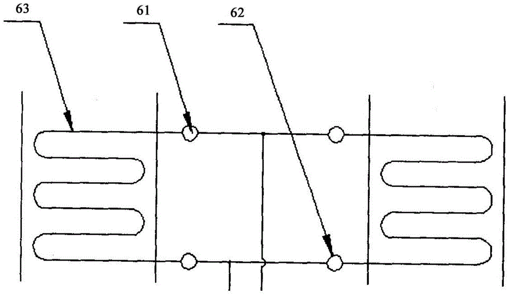
[0038] The flue gas waste heat recovery system 6 in this embodiment includes an inlet header 61, an outlet header 62, and a heat exchange tube bundle 63. The heat exchange tube bundle 63 is a spiral finned tube with a fin pitch of 4mm. Since the flue gas waste heat recovery system 6 in the embodi...
PUM
 Abstract
Description
Claims
Application Information
 - R&D
- Intellectual Property
- Life Sciences
- Materials
- Tech Scout
- Unparalleled Data Quality
- Higher Quality Content
- 60% Fewer Hallucinations
Browse by: Latest US Patents, China's latest patents, Technical Efficacy Thesaurus, Application Domain, Technology Topic, Popular Technical Reports.
© 2025 PatSnap. All rights reserved.Legal|Privacy policy|Modern Slavery Act Transparency Statement|Sitemap|About US| Contact US: help@patsnap.com