Non-contact liquid level detection device and non-contact liquid level detection method

A liquid level detection, non-contact technology, applied in the liquid level indicator of physical variable measurement, etc., can solve the problems of dead angle, float stuck, easy to clean and dirty, etc., to prolong service life, simplify structure, reduce cost effect

Active Publication Date: 2015-04-22
SHANGHAI FLYCO ELECTRICAL APPLIANCE
View PDF5 Cites 44 Cited by
  • Summary
  • Abstract
  • Description
  • Claims
  • Application Information

AI Technical Summary

Problems solved by technology

[0002] As we all know, liquid level detection methods are divided into contact liquid level detection and non-contact liquid level detection. As the name implies, contact liquid level detection means that the sensor and the liquid to be detected are in contact with each other, such figure 1 As shown, this method is relatively simple to implement. The conductive probe or the conductive sheet 6 is directly inserted into the liquid, and the conductivity of the liquid is used. As the liquid level rises, the electrode signal also changes accordingly. When the electrode is energized, an electrolytic chemical reaction will occur. Oxygen will be generated when the water is electrolyzed, and bacteria will easily grow for a long time. At the same time, the conductive electrode will also be corroded, and a large amount of metal ions will be generated in the liquid. However, it is necessary to prevent leakage devices during structural installation, and it is also vulnerable to lightning strikes. In addition, contact liquid level detection is not suitable for liquid level detection of various acid-base, flammable, and high-risk liquids, so people began to turn to non-contact liquid level detection. detection research
[0003] Non-contact liquid level detection means that the sensor and the liquid to be detected are isolated from each other without direct contact. The traditional non-contact liquid level detection methods mainly include ultrasonic detection, laser detection, Hall devices or reed switches with floats (with Magnet) detection methods, etc. Among them, the ultrasonic detection method and the laser detection method both use the reflection principle to detect the liquid level, the cost and installation requirements are high, and there is a certain blind area: while the Hall device or the reed switch cooperates with the float (with a magnet inside) The detection method uses the principle of liquid buoyancy to detect the liquid level, but it has high requirements for structural installation and there is a hidden danger of the float being stuck
like figure 2 As shown, it is a Hall device or reed switch with a float detection structure. The detection device 1 is cylindrical and inserted into the liquid. The float 2 changes along with the liquid level along the detection device 1 and has a magnet 3 inside. At the same time, the detection device 1 is provided with a plurality of sensors 4 in the height direction. When the third or fifth sensor signal disappears, the fourth sensor detects the magnet 3 of the float 2, indicating that the water level is in the fourth grid. To accurately measure the water level , it is necessary to add multiple sensors, and the difficulty of the installation structure is also greatly increased, and it is also necessary to prevent liquid from entering the detection device. At the same time, the sensor 4 uses a reed switch sensor or a Hall sensor with a high cost, which also leads to a high cost
In order to prevent liquid from entering the detection device, such as image 3 As shown, it is another Hall device or reed switch with a float detection structure, and its multiple sensors 4 are directly arranged outside the container, while a float 2 with a magnet 3 is arranged inside the container, and the float 2 is guided up and down. The moving float frame 5 has a relatively simple structure, but when some equipment such as air purification, water purification, and humidification need to regularly clean the container, it is easy to clean uncleanly, there are dead spots, and it is difficult to remove dirt. Need to add multiple sensors, greatly increasing the cost

Method used


Image

  • Non-contact liquid level detection device and non-contact liquid level detection method
  • Non-contact liquid level detection device and non-contact liquid level detection method
  • Non-contact liquid level detection device and non-contact liquid level detection method

Examples


no. 2 example

[0054] The present invention also provides a second embodiment of a non-contact liquid level detection method, which includes:

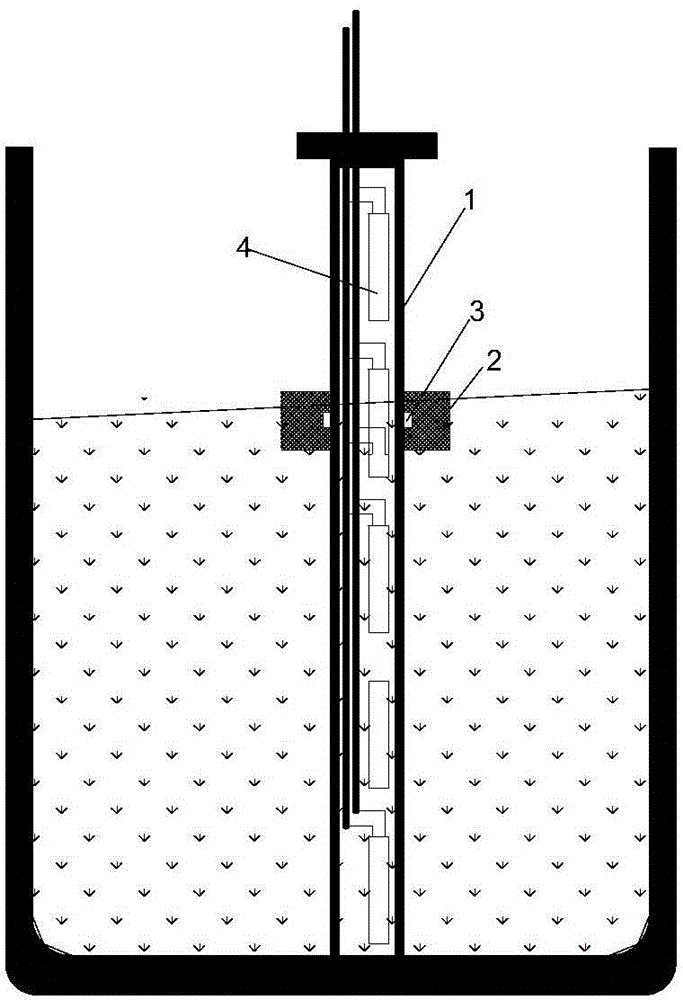
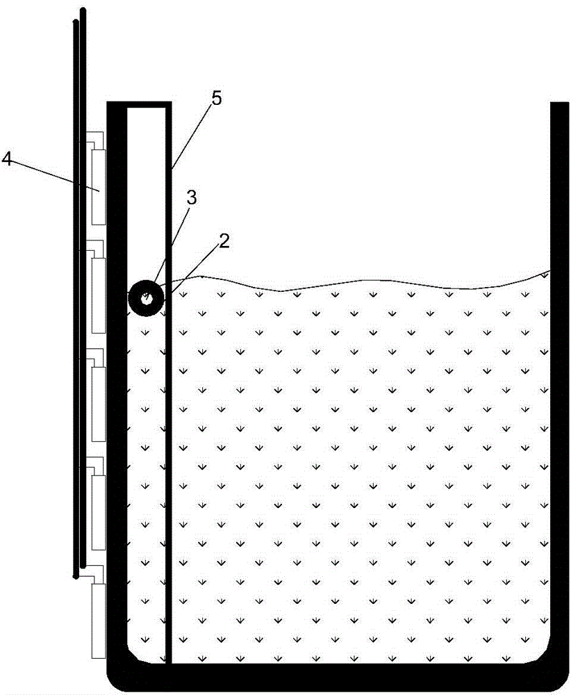
[0055] First provide a detection board 20 located outside the container, at least one sensing unit 21 disposed on the detection board 20, a control unit 22 disposed on the detection board 20 and connected to the output of the at least one sensing unit 21, and the control unit The upper computer 24 connected to the output of 22, wherein the sensing unit 21 is copper clad;

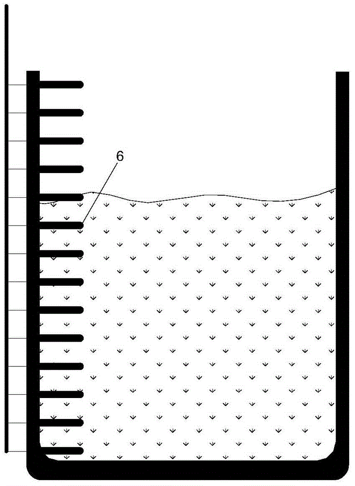
[0056] Then detect the corresponding capacitance value of each sensing unit 21 when the container has no liquid, and store the capacitance value data at this time into the control unit 22 as a reference reference capacitance value; Figure 8 As shown, it is a schematic diagram of the self-capacitance equivalent capacitance distribution. There is an inherent parasitic capacitance Cp (also known as self-capacitance) in one or more sensing units 21 relative to the negative pole of the...


PUM


Abstract

The invention discloses a non-contact liquid level detection device and a non-contact liquid level detection method. The device comprises a detection plate, at least one sensing unit which is arranged on the detection plate at intervals, and a control detection unit which is arranged on the detection plate and is connected with the output of the at least one sensing unit, wherein the liquid level information is obtained by detecting capacitance change through a detection module which is synthesized by the control detection unit and the sensing units by using a CapSense inductive self-capacitance or mutual capacitance detection technology. The device disclosed by the invention is high in detection precision, low in cost and convenient to install and clean a container, can be used for satisfying the demand on most of liquid level detection, and is particularly suitable for being used on home appliances such as a humidifier, a purifier, a water purifier, a coffee machine and the like where the container is needed to be cleaned.

Description

technical field [0001] The invention relates to a non-contact liquid level detection device and method. Background technique [0002] As we all know, liquid level detection methods are divided into contact liquid level detection and non-contact liquid level detection. As the name implies, contact liquid level detection means that the sensor and the liquid to be detected are in contact with each other, such figure 1 As shown, this method is relatively simple to implement. The conductive probe or the conductive sheet 6 is directly inserted into the liquid, and the conductivity of the liquid is used. As the liquid level rises, the electrode signal also changes accordingly. When the electrode is energized, an electrolytic chemical reaction will occur. Oxygen will be generated when the water is electrolyzed, and bacteria will easily grow for a long time. At the same time, the conductive electrode will also be corroded, and a large amount of metal ions will be generated in the liq...

Claims


Application Information

Patent Timeline
Patent Type & Authority Applications(China)
IPC IPC(8): G01F23/26
Inventor 李丐腾
Owner SHANGHAI FLYCO ELECTRICAL APPLIANCE
Why Eureka
Try Eureka