
Direct drive wind turbine simulation test bench and condition monitoring device

A technology of condition monitoring device and wind turbine, which is applied in the direction of motor generator test, measurement device, engine test, etc., can solve the problems of difficulty in determining the degree of failure, lack of effective tracking and feedback of actual failure, lack of excitation load of unit, etc. achieve compact structure

Active Publication Date: 2019-02-01
NORTH CHINA ELECTRIC POWER UNIV (BAODING)
View PDF11 Cites 0 Cited by
  • Summary
  • Abstract
  • Description
  • Claims
  • Application Information

AI Technical Summary

Problems solved by technology

The on-site personnel maintain the unit mainly in the mode of regular tower climbing inspection, and know little about the operating status and possible failure mechanism of the unit. Although some wind turbines are currently equipped with online The vibration data is transmitted to the remote diagnosis center through the network, and the experts conduct remote analysis and processing. However, this mode lacks control over the excitation load of the unit, and it is difficult to determine the fault degree through the vibration signal. The unfavorable phenomenon that the operation state of the wind farm is out of touch with the analysis results

Method used


Image

  • Direct drive wind turbine simulation test bench and condition monitoring device
  • Direct drive wind turbine simulation test bench and condition monitoring device
  • Direct drive wind turbine simulation test bench and condition monitoring device

Examples


Embodiment Construction

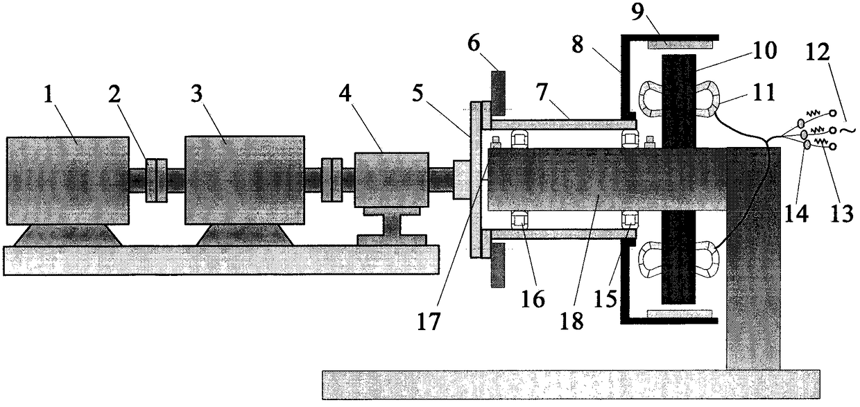
[0019] The present invention provides a direct-drive wind power generator simulation test bench and a state monitoring device. The present invention will be further described below in conjunction with the accompanying drawings and specific embodiments.

[0020] (1) Some kind of fault is man-made on the main bearing of the generator. In this case, it is the burn of the cage. Since the test bench is a modular structure, it is easy to disassemble. The normal bearing and the faulty bearing of the cage are respectively installed on the test platform for testing;

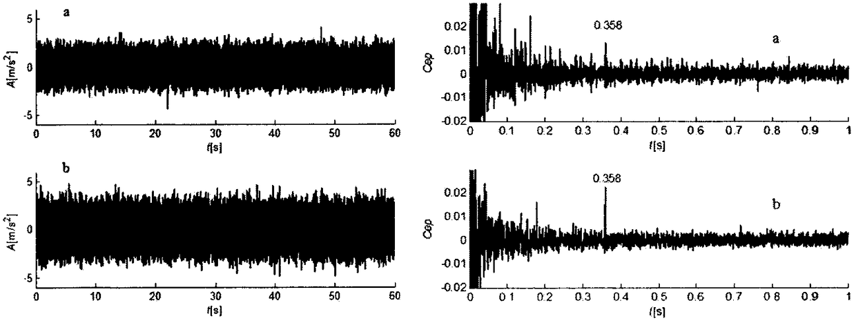
[0021] (2) Acquisition of acceleration vibration signals for analysis, figure 2 The left a is the acceleration signal in the normal state, figure 2 Left b is the acceleration signal when the cage is burned;

[0022] (3) Process the original acceleration signal, such as figure 2 Shown on the right is the corresponding cepstrum signal ( figure 2 The right a is the cepstrum of the normal signal, figure 2 Right b is ...


PUM


Abstract

The invention belongs to the field of state monitoring and fault diagnosis of renewable energy equipment, in particular relates to a simulator stand and a state monitoring device for a direct-driven wind turbine generator, and aims to research operation characteristics and failure mechanism of the direct-driven wind turbine generator and analyze a representation relation between a vibration signal as well as an electric signal and an operation fault of the wind turbine generator. The speed of an asynchronous motor is reduced by virtue of a gearbox and the asynchronous motor is used as a power input of the direct-driven wind turbine generator; the power is transmitted to the direct-driven wind turbine generator through a connecting flange so as to drive a permanent-magnet type external rotor to rotate; a coil mounted on a central shaft of the generator is used as a stator to be fixed and immovable, and the electric energy is transmitted to grid. The direct-driven wind turbine generator adopts a cantilever structure, piezoelectricity acceleration sensors are mounted on a front bearing and a rear bearing of the cantilever structure so as to monitor the state of the bearings; a torquemeter for simultaneously monitoring torque and rotation speed of a transmission chain is arranged on the power input part; a three-phase voltage and current inductor is mounted on a grid combining side of the generator. By analyzing the signals, the operation characteristics and failure mechanism of the direct-driven wind turbine generator can be researched, and a theoretical foundation is provided for operation and maintenance of a real unit.

Description

technical field [0001] The invention belongs to the field of state monitoring and fault diagnosis of energy equipment, and in particular relates to a direct-drive wind power generator simulation test bench and a state monitoring device. Background technique [0002] Horizontal axis wind turbines mainly include two types: doubly-fed asynchronous generators with gearboxes and direct-drive wind turbines without gearboxes. At present, direct-drive wind turbines account for about 1 / 4 of the installed capacity of wind power. With the gradual increase of wind power unit capacity, direct-drive units will become the mainstream of large-scale wind turbines due to their simple transmission chain and compact structure. Since there is no planetary gearbox as a speed-up drive, the direct-drive unit is considered to be a model with a low failure rate. However, in actual operation, the gravity of the blades of the direct drive wind turbine is completely supported by the front bearing, and ...

Claims


Application Information

Patent Timeline
Patent Type & Authority Patents(China)
IPC IPC(8): G01R31/34G01M15/00
Inventor 滕伟姜锐李状柳亦兵
Owner NORTH CHINA ELECTRIC POWER UNIV (BAODING)
Learn More