
Photonic crystal fiber polarizer

A technology of photonic crystal fiber and polarizer, which is applied in polarized fiber, clad fiber, optical waveguide and light guide, etc. It can solve the problems of low communication band coverage and difficult performance adjustment.

Inactive Publication Date: 2015-04-22
HUAZHONG UNIV OF SCI & TECH
View PDF6 Cites 13 Cited by
  • Summary
  • Abstract
  • Description
  • Claims
  • Application Information

AI Technical Summary

Problems solved by technology

Existing manufacturing methods of fiber optic polarizers are different, and each has its own advantages in terms of insertion loss, polarization extinction ratio and transmission bandwidth. However, the coverage of the communication band (1250-1650nm) is generally low, and it is difficult to adjust the performance of the device after it is manufactured. , it is necessary to find a more effective mechanism to meet the needs of the communication and sensing fields

Method used


Image

  • Photonic crystal fiber polarizer
  • Photonic crystal fiber polarizer
  • Photonic crystal fiber polarizer

Examples


Embodiment Construction

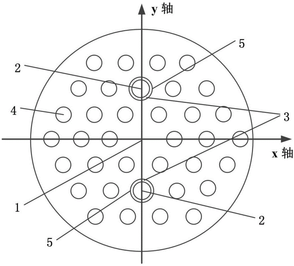
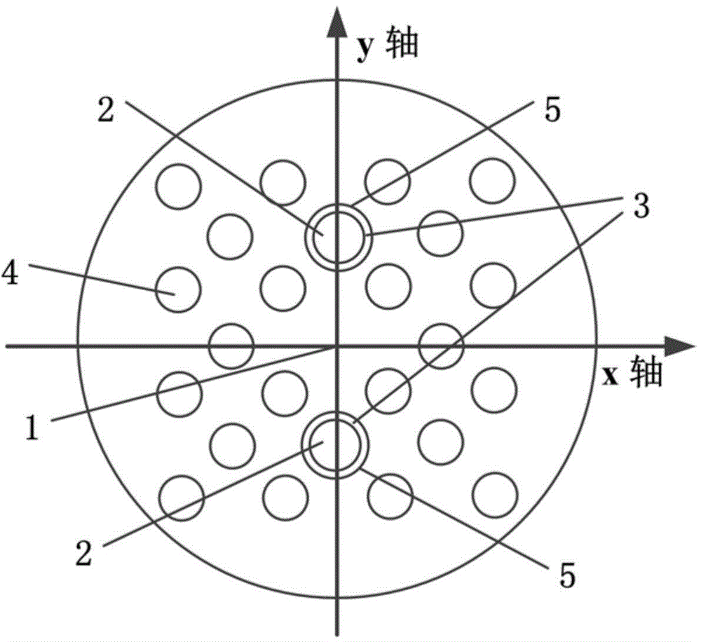
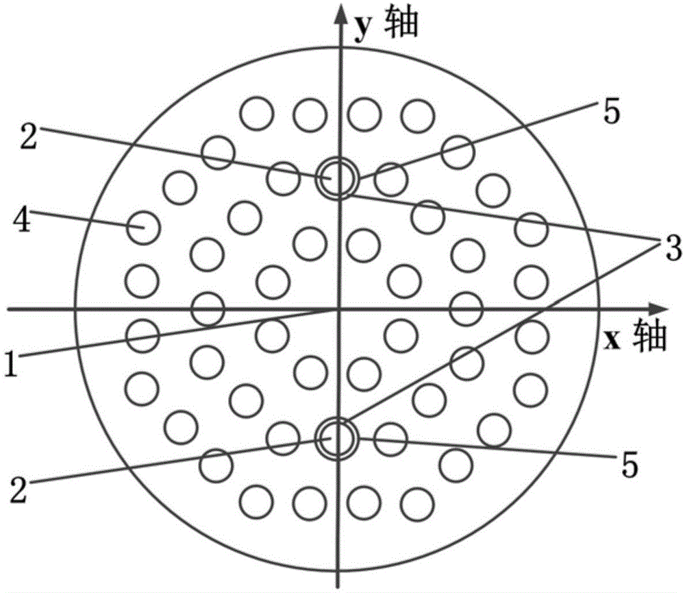
[0020] The photonic crystal fiber is made by the stacking method, the background material is quartz, and an air hole is missing in the center to form a core for conducting the fundamental mode. The hole depth direction of the first air hole is the axial direction of the optical fiber, and the first air hole is distributed in a regular polygon around the fiber core, such as figure 1 As shown, the core 1 of the photonic crystal fiber of the present invention is surrounded by three hexagonal first air holes. That is, the air holes in each circle are arranged in a hexagonal arrangement. Such as figure 2 As shown, the core 1 of the photonic crystal fiber of the present invention is surrounded by three circles of regular quadrilateral first air holes. That is, the air holes in each circle are arranged in four corners. Such as image 3 As shown, the core 1 of the photonic crystal fiber of the present invention is surrounded by three circles of regular octagonal first air holes. ...


PUM


Abstract

The invention discloses a photonic crystal fiber polarizer. The photonic crystal fiber polarizer is a section of photonic crystal fiber comprising a fiber core and cladding. A medium of the cladding is provided with a plurality of first air holes and two second air holes. The hole depth direction of the first air holes is the axial direction of the fiber, and the first air holes are distributed around the fiber core in a regular polygon mode; the two second air holes are located in the diameter part of circular fiber cross sections on the two sides of the fiber core, and there is no first air hole existing between the two second air holes for interference and obstruction; the two second air holes are each internally plated with a metal thin film with the thickness ranging from 20 microns to 90 microns so that coupled metallic waveguide can be formed between the two second air holes. The polarizer breaks through the limitation that the coverage rate of a second communication waveband of an existing fiber polarizer is low, and meanwhile a solution for achieving miniaturization and integration of a communication and sensing system is provided through the temperature adjusting polarization bandwidth character.

Description

technical field [0001] The invention relates to the technical fields of optical fiber communication and optical fiber sensing, in particular to a photonic crystal optical fiber tunable linear polarizer based on the principle of surface plasmon resonance and having ultra-wide bandwidth and high polarization extinction ratio. Background technique [0002] Optical fiber polarizers can convert incident unpolarized light or incompletely polarized light into linearly polarized light polarized in only one direction. It is one of the key components to ensure high-speed optical fiber communication and full-fiber sensor systems and miniaturization. In the optical fiber, due to the birefringence characteristics of the material itself and stress and other factors, the two orthogonal modes in the transmission will undergo polarization mode dispersion and polarization mode coupling, which will cause a series of optical device responses to be affected by random changes in the polarization s...

Claims


Application Information

Patent Timeline
Patent Type & Authority Applications(China)
IPC IPC(8): G02B6/02G02B6/024
CPCG02B6/02314G02B6/024
Inventor 夏历韩雅刘德明
Owner HUAZHONG UNIV OF SCI & TECH
Learn More