Radial vibration annular piezoelectric ceramic composite transformer

A piezoelectric ceramic and annular piezoelectric technology, which is applied in the direction of piezoelectric/electrostrictive/magnetostrictive devices, components and circuits of piezoelectric devices or electrostrictive devices, and can solve the problems affecting piezoelectric ceramics. Transformer performance, weak thermal conductivity, overheating of piezoelectric ceramic transformers, etc.

Inactive Publication Date: 2015-04-22
SHAANXI NORMAL UNIV
View PDF3 Cites 4 Cited by
  • Summary
  • Abstract
  • Description
  • Claims
  • Application Information

AI Technical Summary

Problems solved by technology

The concept of piezoelectric ceramic transformers was proposed by Rosen in the United States in 1954. However, due to the weak thermal conductivity of piezoelectric ceramic materials, overheating of piezoelectric ceramic transformers often occurs, which affects the performance of piezoelectric ceramic transformers.

Method used


Image

  • Radial vibration annular piezoelectric ceramic composite transformer
  • Radial vibration annular piezoelectric ceramic composite transformer
  • Radial vibration annular piezoelectric ceramic composite transformer

Examples


example 1

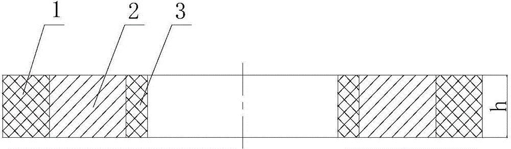
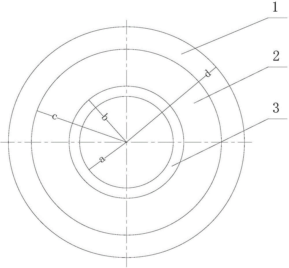
[0066] a=0.01m, b=0.012m, c=0.02m, d=0.024m, h=0.005m, piezoelectric ceramic inner ring 3 and piezoelectric ceramic outer ring 1 are made of PZT-4 material, metal conduction The material of the ring 2 is duralumin, and the load impedance R=50 ohms.

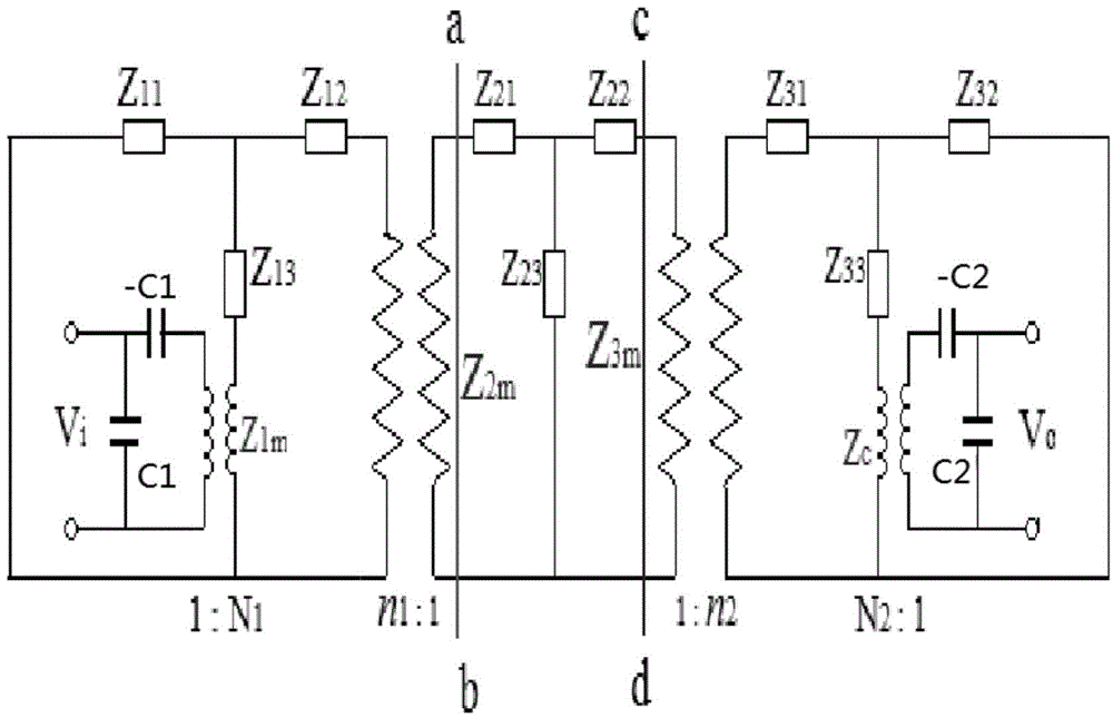
[0067] Utilizing the resonance frequency equation (1) and the voltage gain ratio equation (2), it can be obtained that the operating frequency fr and the anti-resonance frequency fa of the piezoelectric ceramic composite transformer of this embodiment are respectively: fr=39.23kHz, fa=39.74kHz, voltage The gain ratio is M=1.54.

example 2

[0069] a=0.01m, b=0.012m, c=0.02m, d=0.024m, h=0.005m, piezoelectric ceramic inner ring 3 and piezoelectric ceramic outer ring 1 are made of PZT-4 material, metal conduction The material of the ring 2 is duralumin, and the load resistance R=200 ohm.

[0070] Using the resonance frequency equation (1) and the voltage gain ratio equation (2), it can be obtained that the operating frequency fr and the anti-resonance frequency fa of the piezoelectric ceramic composite transformer of this embodiment are respectively: fr=39.46kHz, fa=39.97kHz, the voltage The gain ratio is M=1.57.

example 3

[0072] a=0.01m, b=0.012m, c=0.02m, d=0.026m, h=0.005m, piezoelectric ceramic inner ring 3 and piezoelectric ceramic outer ring 1 are made of PZT-4 material, metal conduction The material of the ring 2 is duralumin, and the load impedance R=50 ohms.

[0073] Utilizing the resonance frequency equation (1) and the voltage gain ratio equation (2), it can be obtained that the operating frequency fr and the anti-resonance frequency fa of the piezoelectric ceramic composite transformer of this embodiment are respectively: fr=36.02kHz, fa=36.42kHz, and the voltage The gain ratio is M=1.69.


PUM


Abstract

The invention relates to a radial vibration annular piezoelectric ceramic composite transformer which comprises a piezoelectric ceramic inner ring and a piezoelectric ceramic outer ring. A metal conducting ring is coaxially arranged between the piezoelectric ceramic inner ring and the piezoelectric ceramic outer ring, the piezoelectric ceramic inner ring, the piezoelectric ceramic outer ring and the upper end face and the lower end face of the metal conducting ring are placed in the same plane, and the height H of the piezoelectric ceramic inner ring, the height H of the piezoelectric ceramic outer ring and the height H of the metal conducting ring are smaller than or equal to D / 6 of the outer diameter of the piezoelectric ceramic outer ring. According to the novel radial vibration annular piezoelectric ceramic composite transformer, the metal circular ring is additionally arranged between an input piezoelectric ceramic device and an output piezoelectric ceramic device, and the effects of improving the radiating of the transformer, enlarging the power capacity of the transformer and improving the electromechanical properties of the transformer can be achieved. Meanwhile, the radial polarized piezoelectric ceramic circular rings are utilized, and the polarization and the excitation orientation of the piezoelectric ceramic circular rings are consistent. The radial vibration annular piezoelectric ceramic composite transformer belongs to a longitudinal effect vibration mode which is similar to a Kt vibration mode, and the electromechanical excitation and conversion efficiency of the piezoelectric ceramic transformer can be improved.

Description

technical field [0001] The invention belongs to the technical field of composite transformers, in particular to a radial vibration annular piezoelectric ceramic composite transformer. Background technique [0002] At present, the traditional way to increase or decrease the alternating voltage is to use an electromagnetic transformer. An electromagnetic transformer is mainly composed of an iron core and a coil surrounding the iron core. In an electromagnetic transformer, the primary and secondary coils are electromagnetically coupled through a magnetic core. In some electrical and high-power electronic applications, large electromagnetic transformers are very effective. However, with the development of science and technology and the miniaturization of electronic devices, many applications in the electronics industry require high-efficiency components with small dimensions, so the demand for small high-efficiency transformers is increasing. Due to its inherent reasons, such...

Claims


Application Information

Patent Timeline
Patent Type & Authority Applications(China)
IPC IPC(8): H01L41/107H01L41/04
Inventor 林书玉
Owner SHAANXI NORMAL UNIV
Why Eureka
Try Eureka