
Pressure-controlled gas drilling device and method

A technology of gas drilling and gas flow, which can be applied in the direction of drilling with liquid/gas jets, etc., and can solve problems such as formation water production

Inactive Publication Date: 2015-04-29
CHINA PETROCHEMICAL CORP +1
View PDF5 Cites 4 Cited by
  • Summary
  • Abstract
  • Description
  • Claims
  • Application Information

AI Technical Summary

Problems solved by technology

[0003] The purpose of the present invention is to solve the problem of formation water production during gas drilling, and to provide a pressure-controlled gas drilling device and method that completely solves the problem of gas drilling formation water production by controlling wellhead pressure and annular pressure

Method used


Image

  • Pressure-controlled gas drilling device and method
  • Pressure-controlled gas drilling device and method
  • Pressure-controlled gas drilling device and method

Examples


Embodiment 1

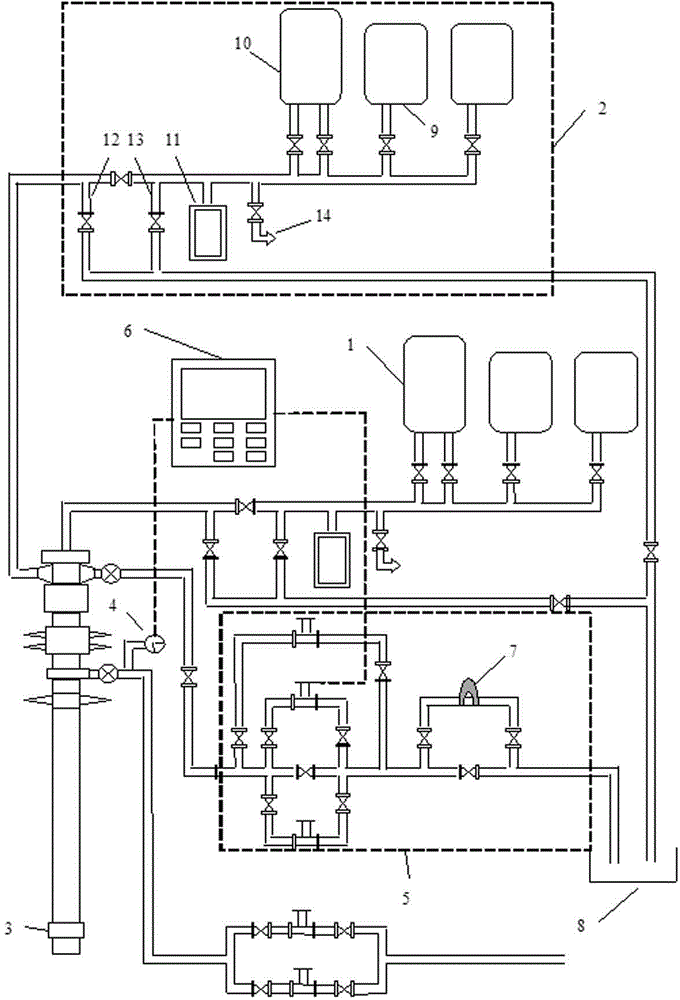
[0053] Attached below figure 1 The device of the present invention is further described.

[0054] The utility model relates to a pressure-controlled gas drilling device, which is modified on the basis of the existing gas drilling device. Existing devices mainly include air pressurization system, wellhead system, air pressure drilling rig and choke manifold of drilling rig, wherein the air booster system includes booster and / or air compressor, gas flow and pressure recorder, pressure relief pipe and / or bypass line, vent line, control valve. The modified device also includes a back pressure system and a fine detail manifold. The wellhead system is equipped with a rotary control head, and the back pressure system and the fine detail manifold are connected to the rotary control head.

[0055] Wherein: the back pressure system includes a supercharger and / or an air compressor, a gas flow and pressure recorder, a pressure relief pipe and / or a bypass pipe, an exhaust pipe, and a co...

Embodiment 2

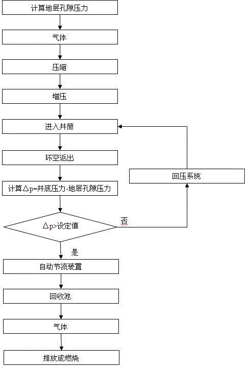
[0059] Refer to attached figure 2 , according to the device pressure-controlled gas drilling method of embodiment 1 is mainly:

[0060] (1) Formation pore pressure is calculated from well logging data, and formation pore pressure is calculated by Terzaghi model:

[0061] P o =P p +σ (1)

[0062] In the formula: P o is the overburden pressure; P p is the formation pore pressure; σ is the vertical effective stress.

[0063] Because the formation stress at different depths with the same acoustic time difference is the same, that is, the degree of formation compaction is the same; the degree of formation compaction is the same, and the skeleton stress of the rock is the same, that is, the same porosity corresponds to the same effective stress.

[0064] If the acoustic time differences of points 1 and 2 are the same and have the same effective stress, then:

[0065] σ 1 = σ 2 (2)

[0066] According to Terzagh formula:

[0067] P o1 =P p1 +σ 1 (3)

[006...


PUM


Abstract

The invention provides a pressure-controlled gas drilling device which comprises an air pressurization system, a wellhead system, an air pressure drilling machine and a drilling machine throttling manifold, wherein the air pressurization system comprises a pressurizer and / or an air compressor, a gas flow and pressure recorder, a pressure release pipe and / or a bypass pipe, an emptying pipe and a control valve, and further comprises a pressure return system and a fine throttling manifold; a rotary control head is arranged on the wellhead system; the pressure return system and the fine throttling manifold are connected with the rotary control head. The invention further provides a pressure-controlled gas drilling method. The method comprises the following steps: calculating formation pore pressure according to logging information; under the condition of normal drilling, retaining formation annulus pressure to be equal to the formation pore pressure through a wellhead throttling valve; when a connection or a trip is made, adjusting and compensating the loss of wellbore circulating pressure by the pressure return system. According to the pressure-controlled gas drilling device, the effect of safe drilling of a complicated formation is well achieved by avoiding the phenomenon of water production on a formation in a gas drilling execution process.

Description

technical field [0001] The invention relates to a pressure-controlled gas drilling device and method in the technical field of gas drilling. Background technique [0002] Gas drilling technology has been widely used in petroleum drilling engineering because of its obvious improvement in drilling speed, good reservoir protection effect, and low comprehensive drilling cost. When water is produced from the formation, after the formation water enters the wellbore, during the gas lift process of the produced water, it is easy to cause hydration expansion of water-sensitive formations such as mud shale and destabilization. After the well wall is unstable, if the collapsed cuttings (blocks) cannot be lifted to the wellhead by the gas in time, it may cause pipe sticking accidents or even well filling, which will bring huge economic losses to oil and gas drilling. It is difficult to give full play to its technical advantages, and the application of gas drilling technology is greatly...

Claims


Application Information

Patent Timeline
Patent Type & Authority Applications(China)
IPC IPC(8): E21B7/18
CPCE21B7/18
Inventor 王宗钢韩来聚李作会冯光通牛洪波魏振赵洪山麻地辉刘晓兰
Owner CHINA PETROCHEMICAL CORP
Learn More