Pulverized coal burner and boiler

A technology for pulverized coal burners and air ducts, which is applied in the direction of burners, burners for burning powder fuel, and combustion methods, etc. It can solve the problems of chaotic air flow field, high carbon monoxide emission concentration, and poor separation effect of pulverized coal air flow. , to achieve the effect of strong adaptability to coal types

Active Publication Date: 2015-04-29
YANTAI LONGYUAN POWER TECH
View PDF7 Cites 10 Cited by
  • Summary
  • Abstract
  • Description
  • Claims
  • Application Information

AI Technical Summary

Problems solved by technology

[0016] The purpose of the present invention is to propose a pulverized coal burner and a boiler equipped with the pulverized coal burner, which solves the problems in the prior art that the concentration separation effect of the pulverized coal air flow is poor, the concentration of carbon monoxide emission is high, the air flow field is chaotic, and the carbon monoxide emission The constraints and contradictions between pulverized coal burnout and NOx emissions lead to the technical problem that it is impossible to effectively suppress the generation of NOx deeply

Method used


Image

  • Pulverized coal burner and boiler
  • Pulverized coal burner and boiler
  • Pulverized coal burner and boiler

Examples


Embodiment approach 1

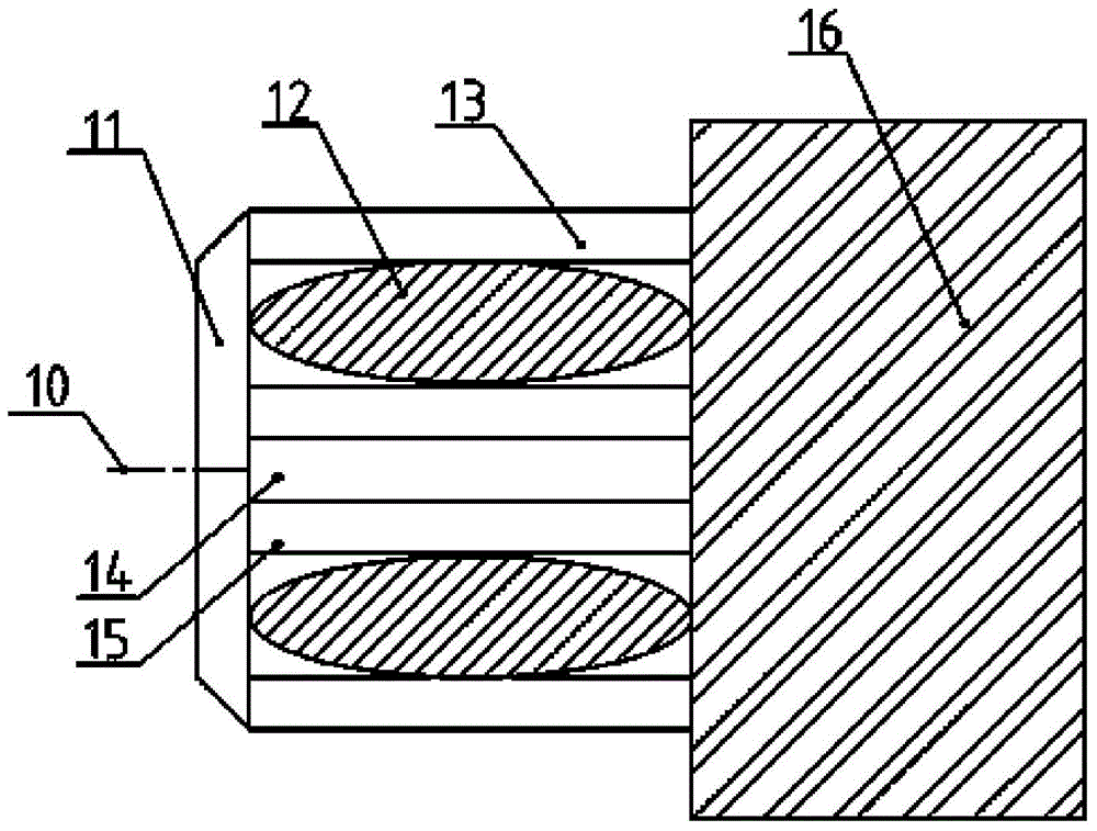
[0065] Such as Figure 4 ~ Figure 5 As shown, the embodiment of the present invention provides a central air cylinder 46, a primary air cylinder 42 and a dual-zone flow field generation structure arranged in the primary air cylinder 42, wherein:

[0066] The primary air duct 42 is sheathed outside the central air duct 46 .

[0067] The double-zone flow field generation structure can make the pulverized coal concentration of the powder-containing airflow sprayed out by the primary air duct 42 through the dual-zone flow field generation structure be distributed in a state of being light on the outside and thick on the inside, and can be distributed in a low-concentration powder-containing airflow. An annular recirculation zone 63 is formed between 65 and the powder-containing airflow 64 with a higher concentration, and a central recirculation zone 62 is formed inside the airflow with a higher concentration.

[0068] The annular recirculation zone 63 and the central recirculatio...

Embodiment approach 2

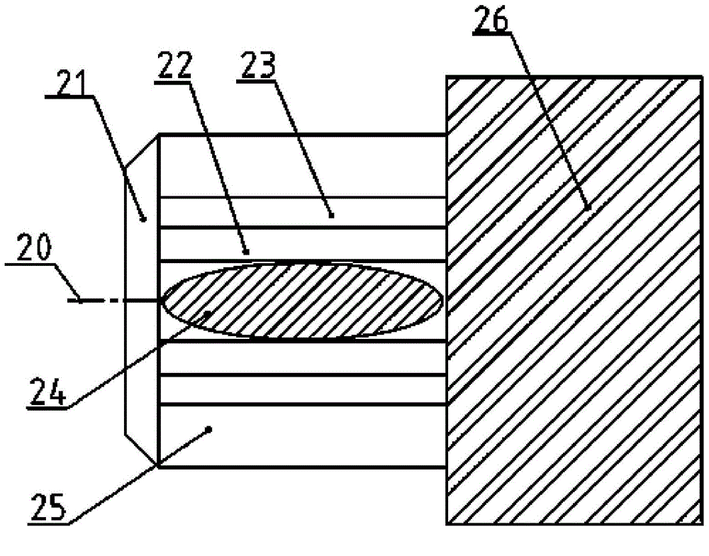
[0116] Such as Figure 6 ~ Figure 7 As shown, this paper also provides another pulverized coal burner, including a central air duct 56, a primary air duct 52, a guide air duct 522, a block 521 and a guide device 524 that can adjust the rigidity or momentum of the pulverized coal airflow , the pulverized coal burner also includes a guide ring 525, wherein:

[0117] The primary air duct 52 is sleeved outside the central air duct 56 .

[0118] The guide air cylinder 522 is located between the downstream section of the central air cylinder 56 and the downstream section of the primary air cylinder 52 .

[0119] The block 521 is fixed on the outer wall of the upstream section of the central air cylinder 56 , the flow guide device 524 is fixed on the outer wall of the air guide tube 522 , and a guide ring 525 is provided at the outlet of the air guide tube 522 .

[0120] The difference from Embodiment 1 provided by the present invention is that Embodiment 2 adopts the structure of ...


PUM


Abstract

Disclosed are a pulverised coal burner and a boiler using the pulverised coal burner, wherein the pulverised coal burner comprises a central air cylinder (46, 56), a primary air cylinder (42, 52) and a twin flow field generating structure provided in the primary air cylinder (42, 52). The primary air cylinder (42, 52) is sheathed outside the central air cylinder (46, 56); the twin flow field generating structure can make the concentration of pulverised coal as an air flow containing powders that passes through the twin flow field generating structure and is injected by the primary air cylinder (42, 52) distributed as sparse on the outside and dense on the inside, and can form an annular recirculation area (12, 32, 63) between a sparsely concentrated air flow containing powders (65) and a highly concentrated air flow containing powders (64), and form a central recirculation area (24, 62, 71) in the highly concentrated air flow containing powders (64). The burner can more effectively inhibit production of NOx.

Description

technical field [0001] The invention relates to pulverized coal combustion technology, in particular to a pulverized coal burner and a boiler provided with the pulverized coal burner. Background technique [0002] The coal market fluctuates and the demand for power supply declines. Most power plants improve corporate efficiency by changing the coal-fired structure. At the same time, the change of the coal-fired structure, that is, the huge difference between the actual coal quality of the boiler and the original design coal quality, causes the flow field of the outlet of the burner to be chaotic, and it is difficult to meet a reasonable flow field, the combustion characteristics of the burner are reduced, and NOx emissions characteristics deteriorate. [0003] NOx is nitric oxide (NO) and nitrogen dioxide (NO 2 ) and other nitrogen oxides, which are mainly derived from fuel combustion products and are a major pollutant in the atmosphere. Among them, power plant boiler pul...

Claims


Application Information

Patent Timeline
Patent Type & Authority Applications(China)
IPC IPC(8): F23D1/02
CPCF23D1/02F23D1/00F23D2201/20
Inventor 唐宏李明林淑胜孙树翁刘欣伊磊王志远姬亚甄晓伟李强李平衣军
Owner YANTAI LONGYUAN POWER TECH
Why Eureka
Try Eureka