Combined steam smoke MGGH system and flue gas treatment technology

A technology of flue gas treatment and steam, which is applied in the direction of lighting and heating equipment, etc. It can solve the problems that the treatment process cannot fully meet the environmental protection requirements, the utilization rate of waste heat of flue gas is low, and the project cost is high, so as to reduce the grade of steam, reduce loss, reduce The effect of corrosion

Inactive Publication Date: 2015-04-29
CHONGQING CLP ENERGY SAVING TECH SERVICE
View PDF7 Cites 8 Cited by
  • Summary
  • Abstract
  • Description
  • Claims
  • Application Information

AI Technical Summary

Problems solved by technology

[0005] In order to meet the requirement that the exhaust gas temperature reaches the specified value, improving the MGGH system will lead to huge equipment, high engineering cost, and the treatment process cann...

Method used


Image

  • Combined steam smoke MGGH system and flue gas treatment technology

Examples


Embodiment 1

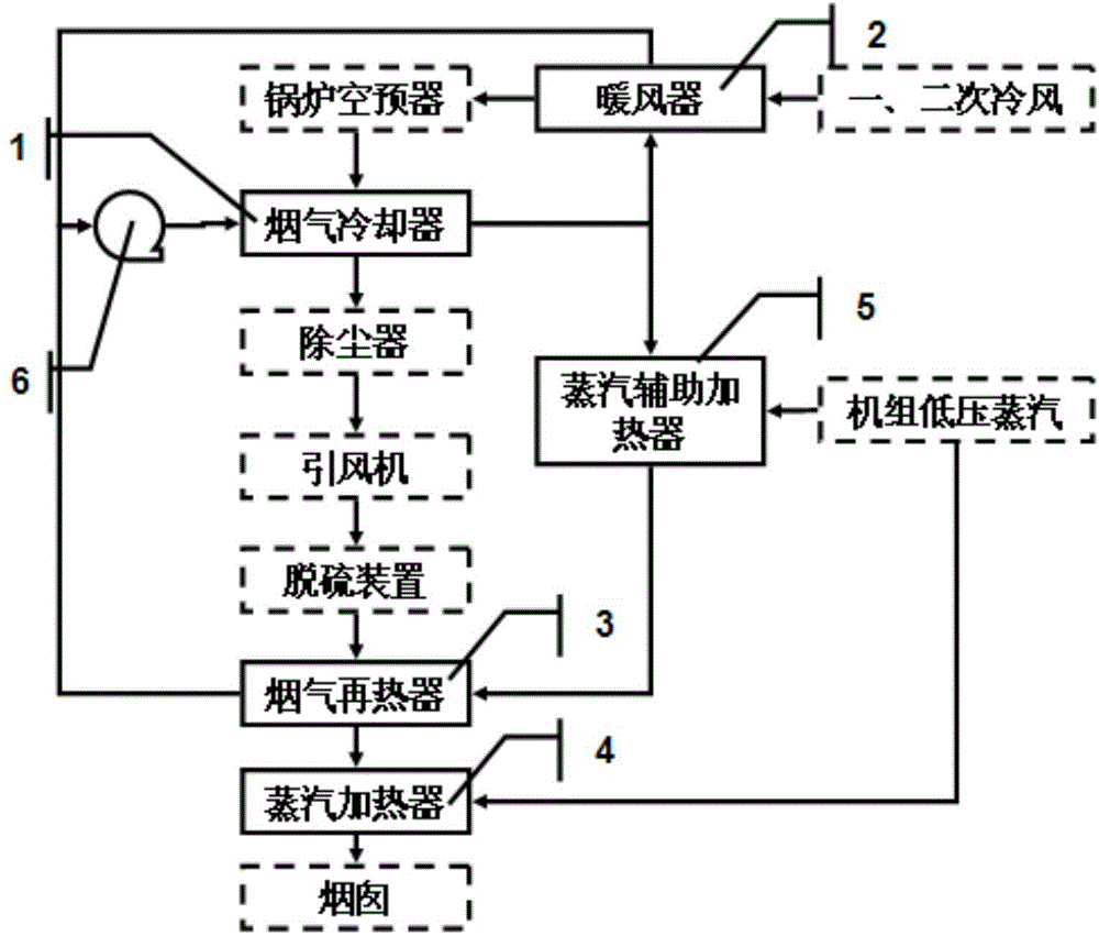
[0034] According to attached figure 1 As shown, this embodiment provides a combined steam flue gas MGGH system. A flue gas cooler 1 is installed on the connecting flue between the boiler air preheater and the dust collector, and a flue gas cooler 1 is installed on the connecting flue between the desulfurization device and the chimney. The flue gas reheater 3 and the steam heater 4, the air heater 2 is installed on the inlet duct of the boiler air preheater, and the steam is installed on the circulating water pipe of the hot section between the flue gas cooler 1 and the flue gas reheater 3 Auxiliary heater 5, a dust collector, an induced draft fan and a desulfurization device are installed between the flue gas cooler 1 and the flue gas reheater 3, and circulating water in the cold section between the flue gas cooler 1 and the flue gas reheater 3 A variable frequency circulation pump set 6 is installed on the pipeline, and a circulating water pipeline connected between the flue ...

Embodiment 2

[0039] This embodiment provides a combined steam flue gas MGGH system. A flue gas cooler 1 is installed on the connecting flue between the boiler air preheater and the dust collector, and a flue gas recooler is installed on the connecting flue between the desulfurization device and the chimney. Heater 3 and steam heater 4, steam auxiliary heater 5 is installed on the hot section circulating water pipeline between flue gas cooler 1 and flue gas reheater 3, and steam auxiliary heater 5 is installed between flue gas cooler 1 and flue gas reheater Set dust collector, induced draft fan and desulfurization device between flue gas cooler 1 and flue gas reheater 3; A circulating water pipeline valve adjustment system connected between the gas reheater 3, steam auxiliary heater 5 and frequency conversion circulating pump group 6 is installed, and a steam and condensed water pipeline valve adjustment system is installed on the steam heater 4 and steam auxiliary heater 5.

[0040] Using ...

Embodiment 3

[0050] This embodiment provides a combined steam flue gas MGGH system. A flue gas cooler 1 is installed on the connecting flue between the boiler air preheater and the dust collector, and a flue gas recooler is installed on the connecting flue between the desulfurization device and the chimney. Heater 3 and steam heater 4, the heater 2 is installed on the inlet air duct of the boiler air preheater, and the steam auxiliary heater is installed on the hot section circulating water pipe between the flue gas cooler 1 and the flue gas reheater 3 5. Install dust collector, induced draft fan and desulfurization device between flue gas cooler 1 and flue gas reheater 3, and install on the cold section circulating water pipeline between flue gas cooler 1 and flue gas reheater 3 Frequency conversion circulating pump unit 6, a circulating water pipeline valve adjustment system connected between flue gas cooler 1, heater 2, flue gas reheater 3, steam auxiliary heater 5 and frequency conversi...


PUM


Abstract

The invention provides a combined steam smoke MGGH system. The combined steam smoke MGGH system comprises a boiler air pre-heating device, wherein the boiler air pre-heating device is connected with a flue gas cooler, the flue gas cooler is connected with a dust remover, the dust remover is connected with an induced draft fan, the induced draft fan is connected with a desulfurization device, the desulfurization device is connected with a flue gas re-heating device, the flue gas re-heating device is connected with a steam heater, and the steam heater is connected with a chimney. The combined steam smoke MGGH system is characterized in that the steam heater is arranged between the flue gas re-heating device and the chimney, a steam auxiliary heater is arranged between the flue gas cooler and the flue gas re-heating device, and the flue gas re-heating device is connected with the flue gas cooler through a variable frequency circulating pump. The combined steam smoke MGGH system and a flue gas treatment technology thereof mainly solve the problem that due to the fact that flue gas temperature is not high enough, an existing MGGH system uses steam to assist in heating, and can significantly reduce steam consumption and engineering cost investment.

Description

technical field [0001] The invention belongs to the field of cleaning flue gas after desulfurization by using waste heat of flue gas in electric power or similar industries, and in particular relates to a combined steam flue gas MGGH system and a flue gas treatment process. Background technique [0002] In order to protect air quality, thermal power plants have adopted flue gas desulfurization technology. Basically, the wet desulfurization system is adopted, and the net flue gas after the desulfurization absorption tower is discharged to the atmosphere through the chimney. However, the clean flue gas after desulfurization is discharged directly without heating. Regardless of whether the flue and chimney have taken anti-corrosion measures, the acid gas in the wet flue gas will be absorbed when passing through the condensate droplets on the inner wall of the flue and chimney, forming strong acidity. The liquid corrodes and damages the wear-resistant materials on the inner wal...

Claims


Application Information

Patent Timeline
IPC IPC(8): F23J15/00F23J15/08
Inventor 熊志成罗先辉
Owner CHONGQING CLP ENERGY SAVING TECH SERVICE
Why Eureka
Try Eureka