
Laser annealing equipment and method for improving silicon wafer surface roughness by adopting laser annealing equipment

A laser annealing, silicon wafer surface technology, applied in laser welding equipment, welding equipment, metal processing equipment, etc., can solve the problems of prone to debris, increase process time and cost, and achieve the effect of improving roughness

Inactive Publication Date: 2015-04-29
SHANGHAI HUAHONG GRACE SEMICON MFG CORP
View PDF4 Cites 0 Cited by
  • Summary
  • Abstract
  • Description
  • Claims
  • Application Information

AI Technical Summary

Problems solved by technology

In order to improve the adsorption capacity of the metal on the back, it is necessary to roughen the surface of the silicon wafer. However, additional roughening steps require re-purchase of equipment, which will also increase the cost of process time. More importantly, many mechanical roughening treatments are likely to cause microcracks. These microcracks are prone to fragmentation during laser annealing.

Method used


Image

  • Laser annealing equipment and method for improving silicon wafer surface roughness by adopting laser annealing equipment
  • Laser annealing equipment and method for improving silicon wafer surface roughness by adopting laser annealing equipment

Examples


Embodiment Construction

[0009] In order to have a more specific understanding of the technical content, characteristics and effects of the present invention, now in conjunction with the accompanying drawings, the details are as follows:

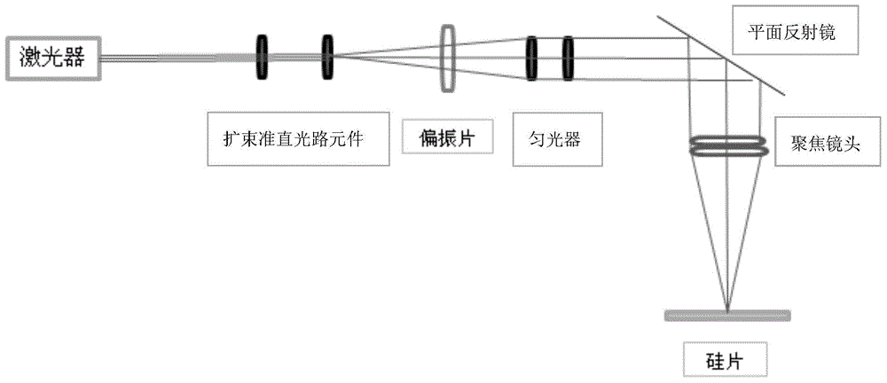
[0010] In this embodiment, the optical path system of the laser annealing equipment has been newly designed and transformed, such as figure 1 As shown, in addition to the conventional optical components such as the original laser, beam expander and collimator optical path elements, homogenizer and focusing lens, a set of polarizers is added between the beam expander collimator optical path elements and the light homogenizer, so that The laser light emitted by the laser becomes polarized light with a fixed direction after passing through the set of polarizers.

[0011] Polarizers include but not limited to 1 / 4, 1 / 2 waveplates. The number of polarizers can be one piece or one set. The polarization direction is not particularly limited, and may be any direction.

[...


PUM

PropertyMeasurementUnit
surface temperatureaaaaaaaaaa

Abstract

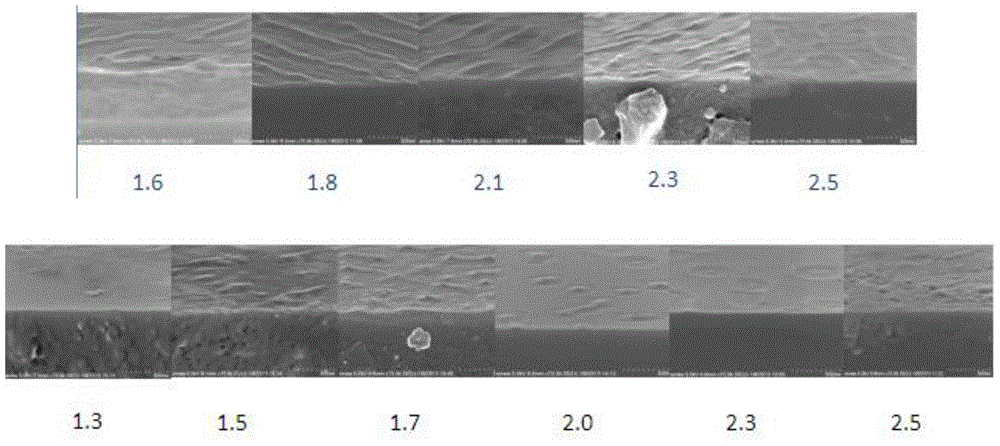
The invention discloses laser annealing equipment. Besides the original conventional optical components such as a laser, a beam expanding and collimating optical path component, a dodging device, a focusing lens and the like in an optical path, more than one polarizer is mounted between the beam expanding and collimating optical path component and the dodging device. The invention discloses a method for improving the silicon wafer surface roughness by adopting the laser annealing equipment. According to the method, polarized laser is used for irradiating the silicon wafer surface after the laser output energy is higher than 1.0 J / cm<2> and the silicon wafer surface temperature is higher than 1,400 DEG C, so that stripe-shaped fluctuation is formed on the silicon wafer surface. According to the laser annealing equipment, a group of polarized optical lenses are added to an original optical path, and polarized light in the fixed direction is formed; the high temperature characteristic of laser annealing is used, and fluctuated strips are formed on a silicon wafer during annealing, so that the wafer surface roughness and the metal absorbing and sputtering firmness are improved under the condition that equipment and process steps are not added.

Description

technical field [0001] The invention relates to the field of integrated circuit manufacturing, in particular to a method for treating the surface roughness of a silicon chip before back metal sputtering. Background technique [0002] In IGBT (insulated gate bipolar transistor) and other processes, it is necessary to perform back metal sputtering after ion implantation and laser annealing processes are completed on the back sheet. Since there is generally no long film and other processes on the back, the surface of the silicon wafer is mirror smooth. , the metal is not easy to absorb, and it is easy to cause the phenomenon of metal peeling. In order to improve the adsorption capacity of the metal on the back, it is necessary to roughen the surface of the silicon wafer. However, additional roughening steps require re-purchase of equipment, which will also increase the cost of process time. More importantly, many mechanical roughening treatments are likely to cause microcracks....

Claims


Application Information

Patent Timeline
Patent Type & Authority Applications(China)
IPC IPC(8): H01L21/268B23K26/06
CPCH01L21/268B23K26/06
Inventor 童宇锋郑刚刘国淦
Owner SHANGHAI HUAHONG GRACE SEMICON MFG CORP
Learn More