Multi-stall movable charging method and device

A charging device and mobile technology, applied in charging stations, circuit devices, battery circuit devices, etc. for charging mobile devices, can solve problems such as the inability to charge multiple electric vehicles at the same time, large battery loss, and slow charging speed, etc., to achieve The effect of fast charging speed, high charging efficiency and low loss

Inactive Publication Date: 2015-04-29
HUNAN PUYUN INTELLIGENT TECH
View PDF5 Cites 11 Cited by
  • Summary
  • Abstract
  • Description
  • Claims
  • Application Information

AI Technical Summary

Problems solved by technology

In the prior art, the integrated structure of charging pile, charging power supply and charging motor is adopted. In this way, when multiple electric vehicles are charged at the same time, the pressure on the urban power grid will be doubled. Transform the power grid, such as the electric vehicle charging station disclosed in the invention patent application with the publication number CN104218635. In this invention patent application, the existing fixedly installed charging pile is changed into a movable charging device, although the existing charging plug has been solved. The problem is that it needs to be manually connected to the vehicle for charging, but the integrated structure of the charging power supply, the charging motor and the charging pile is adopted, and due to the design defects of the track, the movable charging equipment cannot be moved to each vehicle in a horizontal and vertical coordinate Next to the parking space, the electric vehicles are connected one by one to charge. The charging device uses a software system to read the battery power information of the electric vehicles and forms a queue for orderly charging. The charging speed is slow and the battery loss is large, and it is still impossible to realize multiple electric vehicles. The need for simultaneous charging of cars

Method used


Image

  • Multi-stall movable charging method and device

Examples


Embodiment Construction

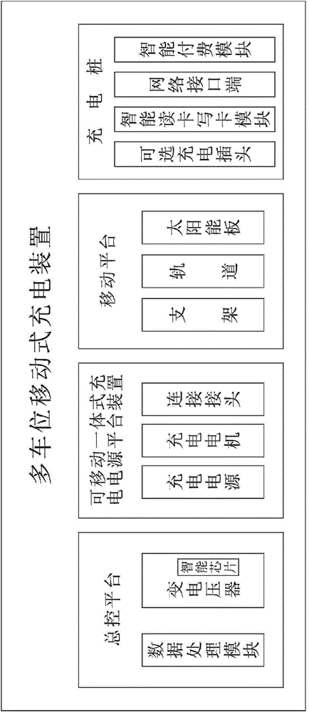
[0025] Such as figure 1 Shown, the concrete structural feature of the present invention is:

[0026] A mobile charging method with multiple parking spaces, characterized in that the method comprises:

[0027] There is a transformer on the master control platform, which can transform the AC power of 220V-380V into DC power of 450V-480V;

[0028] Set up a special movable integrated charging power platform device, and set it separately from the charging pile, and set up a mobile platform above the charging pile next to the parking space or on the ground, so that the movable integrated charging power platform device can be placed on each charging pile along the mobile platform. parallel movement between

[0029] A connecting joint is slidably arranged on one side of the movable integrated power supply platform device, and the connecting joint is used for docking connection with the charging pile, that is, when the movable integrated charging power supply platform device moves in...


PUM


Abstract

The invention discloses a multi-stall movable charging method and device. The multi-stall movable charging device is characterized by comprising a master control platform, a movable integrated charging power source platform device, a movable platform and a charging pile; the master control platform is provided with a voltage transformer, the movable integrated charging power source platform device is separated from the charging pile, the movable platform is arranged above or on the peripheral ground of the charging pile beside a stall, a connector in abut connection with the charging pile is arranged on one side of the movable integrated charging power source platform device, direct current electricity converted by the voltage transformer is in abut connection with the charging pile through the movable integrated charging power source platform device to output a charging power source, the power supply voltage of the voltage transformer is automatically adjusted according to a configured intelligent chip, and charging voltage is provided for multiple electric cars by the voltage transformer within the range of loads of a power grid. The multi-stall movable charging method and device realize intelligent charging of electric cars, the power grid does not need to be modified, and the multi-stall movable charging device can be used in various medium and small parking lots or underground garages through the existing power grid voltage.

Description

technical field [0001] The invention relates to a multi-slot mobile charging method and device for a new energy electric vehicle. Background technique [0002] With the country building a low-carbon environment-friendly economy and the development of new energy strategies and the increasingly mature technology of electric vehicles, major cities are currently increasing the promotion and application of electric vehicles, and how to solve the charging problem of electric vehicles has become a major issue for the promotion of electric vehicles. An important part of the application. In the prior art, the integrated structure of charging pile, charging power supply and charging motor is adopted. In this way, when multiple electric vehicles are charged at the same time, the pressure on the urban power grid will be doubled. Transform the power grid, such as the electric vehicle charging station disclosed in the invention patent application with the publication number CN104218635. ...

Claims


Application Information

Patent Timeline
Patent Type & Authority Applications(China)
IPC IPC(8): H02J7/02
CPCB60L53/30H02J7/0027H02J7/0071Y02T10/70Y02T10/7072Y02T90/12
Inventor 王忠叶常富
Owner HUNAN PUYUN INTELLIGENT TECH
Why Eureka
Try Eureka