

Equipment for performing modified treatment on medium and large particle seeds by using cold plasma
A technology of cold plasma and processing equipment, applied in the field of biological seed processing devices, can solve the problems of increased working vacuum, short processing time, difficult ignition, etc. Efficient effect
- Summary
- Abstract
- Description
- Claims
- Application Information
AI Technical Summary
Problems solved by technology
Method used
Image

Examples
Embodiment Construction
[0030] The present invention will now be further described in detail in conjunction with the accompanying drawings and embodiments. These drawings are all simplified schematic diagrams, only illustrating the basic structure of the present invention in a schematic manner, so it only shows the composition related to the present invention.
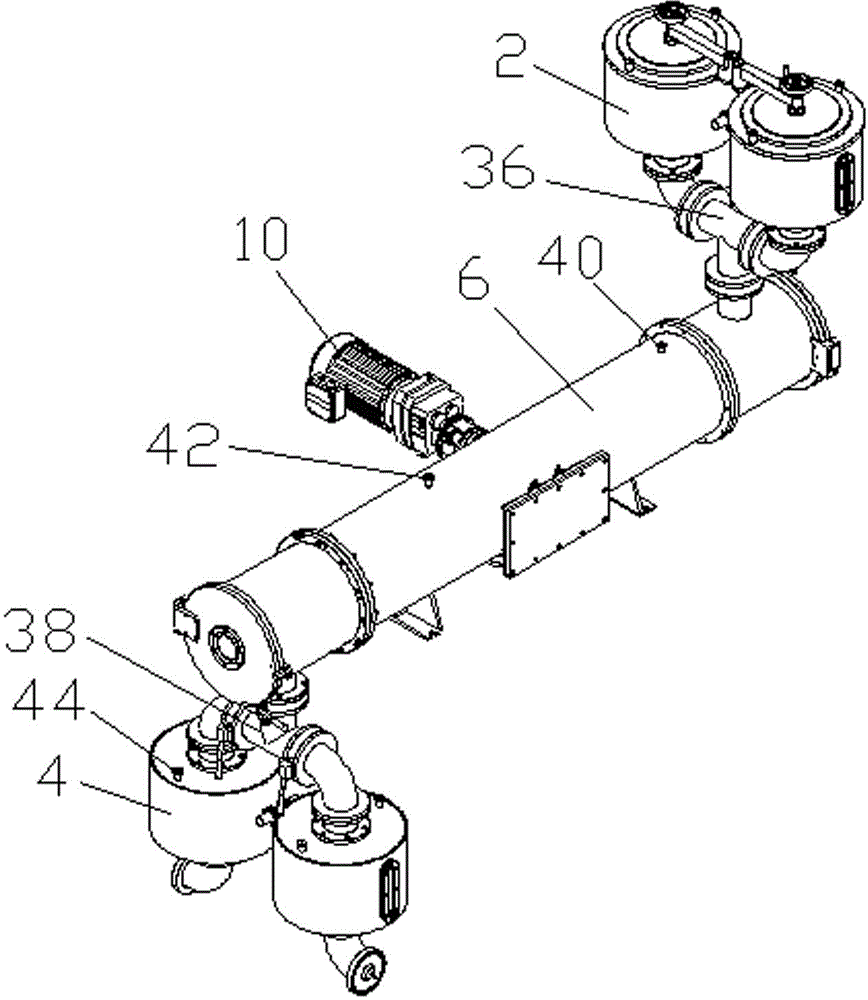
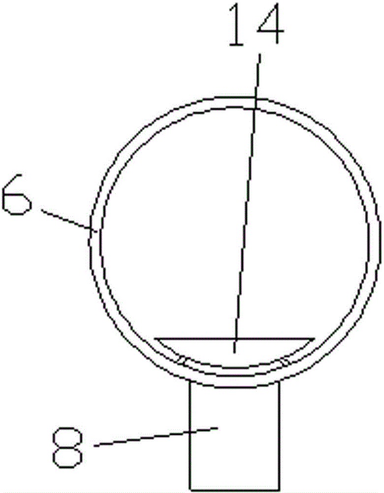
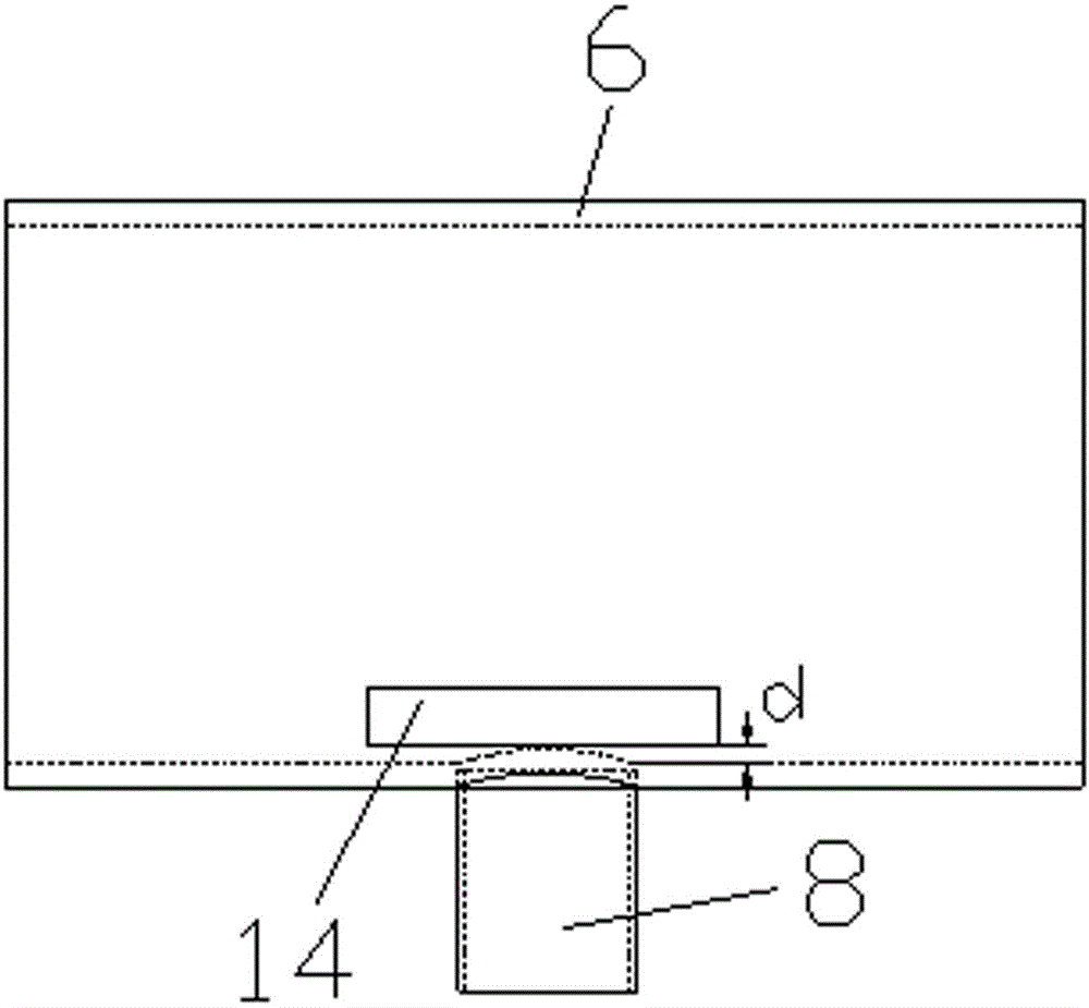
[0031] like Figure 1-Figure 4 As shown, a kind of cold plasma treatment equipment for modifying medium and large particle seeds, including an upper material bucket 2, a lower material bucket 4, and a vacuum chamber 6 connecting the upper material bucket 2 and the lower material bucket 4, the vacuum chamber 6 A pumping port 8 is provided on the top, and the pumping port 8 is connected with a mechanical pump 10. A discharge processing device and a transmission device are arranged in the vacuum cavity 6. The discharge processing device includes two pole plates 12 arranged in parallel, and the two pole plates 12 are in phase with each other. Con...
PUM
 Abstract
Description
Claims
Application Information