Forming method of backplane and backplane

A backplane and bottom plate technology, applied in metal processing, circuits, semiconductor devices, etc., can solve the problems of cover plate deformation, cost a lot of manpower and time, and assembly difficulty coefficient, so as to reduce assembly difficulty, improve assembly accuracy, and improve The effect of welding bond rate

Active Publication Date: 2016-07-20
KONFOONG MATERIALS INTERNATIONAL CO LTD
View PDF6 Cites 1 Cited by
  • Summary
  • Abstract
  • Description
  • Claims
  • Application Information

AI Technical Summary

Problems solved by technology

[0010] In the prior art, the assembly difficulty coefficient of the cover plate, the solder, and the bottom plate is high, and the welding bonding rate of the formed back plate is low
In addition, the gap between the side wall of the target installation groove of the base plate and the side wall of the cover plate will be filled with solder. The solder in this gap will seriously affect the appearance of the back plate, and it will take a lot of manpower and time to fill the gap. During the process of removing the solder at the gap, it is easy to deform the cover plate

Method used


Image

  • Forming method of backplane and backplane
  • Forming method of backplane and backplane
  • Forming method of backplane and backplane

Examples


Embodiment Construction

[0046] After research, in the prior art, the assembly difficulty coefficient of the cover plate, the solder, and the bottom plate is high, and the welding bonding rate of the formed back plate is low. In addition, there will be solder in the gap between the side wall of the target installation groove of the bottom plate and the side wall of the cover plate. The solder in this gap will seriously affect the appearance of the back plate, and it will take a lot of manpower and time to fix the gap. In the process of removing the solder at the gap, the reason why the cover plate is easy to deform is as follows:

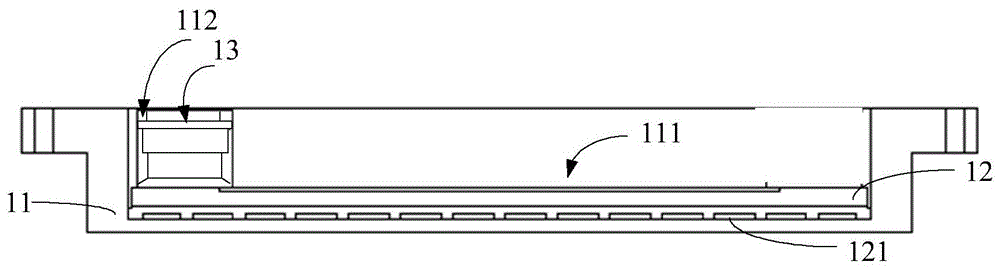
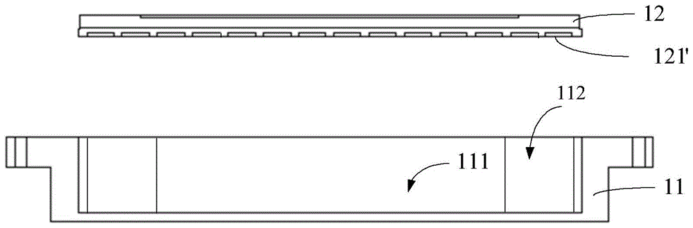
[0047] In the prior art, the brazing filler metal has a flake structure. Put the brazing material on the bottom front of the target mounting groove 111, and firstly put the brazing material in contact with the side of the cover plate 12 that has the cooling water channel groove structure 121', specifically, the brazing material and the cooling water channel groove structure...


PUM


Abstract

Provided are a method for forming a backboard and the backboard. The method for forming the backboard comprises the steps that a bottom plate and a cover plate are provided, the surface, facing one side of the cover plate, of the bottom plate is the top face of the bottom plate, the top face of the bottom plate is a plane, the bottom face of the cover plate is a plane, and cooing water channel slot structures are arranged on the bottom of the cover plate; the cooling water channel slot structures and the bottom plate form cooling water channels; the bottom face of the cover plate and the top face of the bottom plate are welded through the brazing technique to form the backboard. By the adoption of the method, the assembly difficulty coefficient of the cover plate, brazing filler metal and the bottom plate can be reduced, and the formed backboard is high in soldering binding rate. In addition, the cover plate is not prone to deformation.

Description

technical field [0001] The invention relates to the field of semiconductors, in particular to a method for forming a backplane and the backplane. Background technique [0002] In the vacuum sputtering process, the target assembly is composed of a target that meets the sputtering performance and a back plate with a certain strength. The back plate not only plays a supporting role in the target assembly, but also has the effect of conducting heat, so it is used for heat dissipation of the target in the vacuum sputtering process. Specifically: [0003] In the vacuum sputtering process, the working environment of target components is relatively harsh. Its temperature is high (such as 300°C to 500°C), the target component is in a high-voltage electric field and a magnetic field with high magnetic field strength, and the front surface is at 10 -9 Under the high-vacuum environment of Pa, it is bombarded by various high-energy ions, causing the target to be sputtered, and the spu...

Claims


Application Information

Patent Timeline
Patent Type & Authority Patents(China)
IPC IPC(8): B23K1/008C23C14/34
CPCB23K1/008B23K2101/40C23C14/34
Inventor 姚力军相原俊夫大岩一彦潘杰王学泽吴豪杰
Owner KONFOONG MATERIALS INTERNATIONAL CO LTD
Why Eureka
Try Eureka