A butterfly plate hydraulic automatic combination device of a butterfly valve assembly machine and its combination method

A butterfly valve and automatic combination technology, which is applied in metal processing equipment, metal processing, manufacturing tools, etc., can solve the problems that processing and manufacturing cannot meet the demand, it is difficult to meet the needs of the market and users, and the cost of repair and maintenance is increased. , to achieve the effect of improving work efficiency and product quality, saving maintenance costs and production costs, and facilitating promotion

Active Publication Date: 2017-01-25
BAND VALVE TECH CO LTD
View PDF6 Cites 1 Cited by
  • Summary
  • Abstract
  • Description
  • Claims
  • Application Information

AI Technical Summary

Problems solved by technology

[0002] At present, butterfly valves are widely used in chemical engineering, water conservancy, fire protection, engineering and other pipeline machinery fields due to their advantages of convenient control, safety, wear resistance, and engineering; with the rapid development and renewal of various fields, existing butterfly valves The processing and manufacturing of butterfly valves can no longer meet the demand; traditional butterfly valve manufacturers, when producing and assembling the rubber sleeves of butterfly valves, are basically assembled by hand, that is, the rubber sleeves and butterfly plates are manually driven into the valve with a hammer. In vivo, there are the following shortcomings: different processes require different people to assemble, and the technical requirements are high; time-consuming, it takes more than 10 minutes from the first step to the last step; laborious, from the first step to the last step , the labor intensity is relatively high; due to the requirements of processing standards, it is easy to be biased during the assembly process, damage, bias and other losses, often reworked many times to meet the standard; the efficiency is low
[0003] Therefore, there are many advanced technologies and professionals in this field, who have continuously improved and adjusted the butterfly valve assembly machinery for a long time to meet the needs of development; however, the existing butterfly plate assembly machinery for butterfly valves is already very advanced, but the operation It is not convenient enough, and the main control hydraulic pressure cannot be adjusted and controlled in time according to the model and specification according to the processing standard. Once a failure occurs, the repair and maintenance cost will be increased, and the work efficiency will be reduced; When the plates are assembled and assembled, the safety factor of the main machine of the existing butterfly valve assembly machine is low, resulting in deformation of the butterfly plates of different specifications and models when assembled and pressed by the existing butterfly valve assembly machine, which affects the quality of the butterfly valve; Then, when assembling the butterfly discs of the butterfly valve, the finished product rate of the processed butterfly valve needs to be further improved to reduce the consumption of additional energy resources; for a long time, it has been the bottleneck in the development of this field, affecting the development of butterfly valve assembly machinery, and it is difficult to meet the needs of the market and user needs

Method used


Image

  • A butterfly plate hydraulic automatic combination device of a butterfly valve assembly machine and its combination method
  • A butterfly plate hydraulic automatic combination device of a butterfly valve assembly machine and its combination method
  • A butterfly plate hydraulic automatic combination device of a butterfly valve assembly machine and its combination method

Examples


Embodiment 1

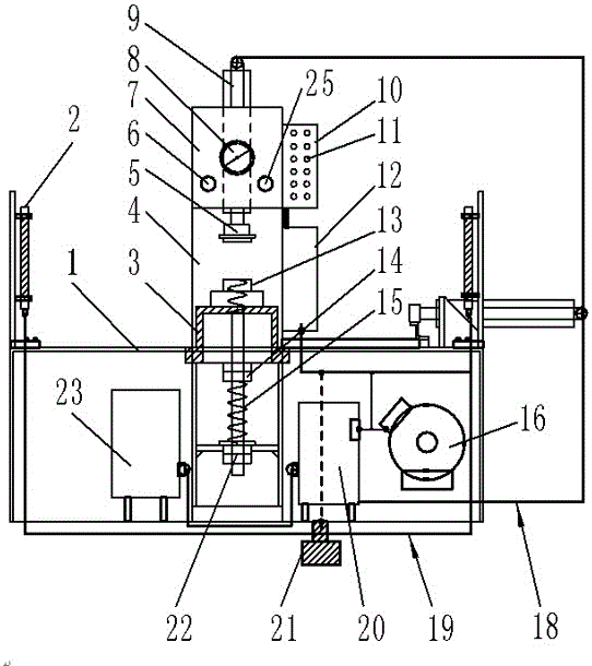
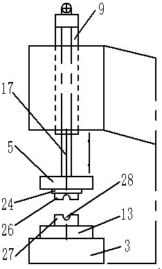
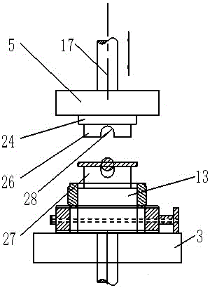
[0041] As shown in the figure, a butterfly plate hydraulic automatic combination device of a butterfly valve assembly machine consists of a butterfly valve assembly workbench 1, an infrared sensor safety device 2, a tooling base 3, an assembly machine column 4, a pressure head tooling 5, and a pressure regulating valve. Device 6, upper hydraulic cylinder support frame 7, pressure gauge 8, upper hydraulic cylinder device 9, PLC control box device 10, control button 11, electrical box device 12, butterfly valve tooling 13, lock nut mechanism 14, lower screw screw assembly Cheng 15, motor device 16, piston rod device 17, hydraulic system pipeline 18, signal system circuit 19, hydraulic pump device 20, foot switch mechanism 21, limit lock female device 22, hydraulic oil tank device 23, butterfly valve assembly retaining ring 24. The pressure gauge switch device 25, the movable pressure head device 26, the positioning pressure head device 27, the butterfly plate bushing slot 28, and...

Embodiment 2

[0053] As shown in the figure, a combination method of butterfly plate hydraulic automatic combination device of butterfly valve assembly machine, the specific process steps are as follows:

[0054] First of all, prepare for work; organize and prepare the working and operating conditions according to the management standards of the factory above 6s, and check the condition of each component of the butterfly valve assembly machine; ensure that the hydraulic oil in the hydraulic oil tank device 23 is not lower than the lower limit of the liquid level gauge, and the electrical box device The power supply of 12 is safe and normal;

[0055] Secondly, carry out the test run; open the electrical box device 12, close each switch of the machine, the power indicator light is on, start the electro-hydraulic control butterfly valve automatic assembly machine; check the steering of the motor device 16, the fan blade is set to rotate clockwise, Loosen the pressure gauge switch device 25, ad...

Embodiment 3

[0062] As shown in the figure, a combination method of butterfly plate hydraulic automatic combination device of butterfly valve assembly machine, the specific process steps are as follows:

[0063] First of all, prepare for work; organize and prepare the working and operating conditions according to the management standards of the factory above 6s, and check the condition of each component of the butterfly valve assembly machine; ensure that the hydraulic oil in the hydraulic oil tank device 23 is not lower than the lower limit of the liquid level gauge, and the electrical box device The power supply of 12 is safe and normal;

[0064] Secondly, carry out the test run; open the electrical box device 12, close each switch of the machine, the power indicator light is on, start the electro-hydraulic control butterfly valve automatic assembly machine; check the steering of the motor device 16, the fan blade is set to rotate clockwise, Loosen the pressure gauge switch device 25, ad...


PUM


Abstract

The invention relates to an assembly machine and a combination method thereof, in particular to a butterfly plate hydraulic automatic combination device for a butterfly valve assembly machine and the combination method thereof. The butterfly plate hydraulic automatic combination device consists of a butterfly valve assembly workbench, infrared sensing safety devices, a tool base, an assembly machine upright post, a pressure head tool, a pressure regulating valve device, an upper hydraulic oil cylinder support frame, a pressure meter, an upper hydraulic cylinder device, a PLC (Programmable Logic Controller) control box device, control buttons, an electrical cabinet device, a butterfly valve tool, a locking nut mechanism and the like. The butterfly plate hydraulic automatic combination device is convenient and safe to use and is rapid to operate, the pressure of a host machine can be adjusted in time according to butterfly valve rubber sleeves and butterfly plates of different models and specifications; working efficiency and quality are greatly improved, the yield is over 99 percent, machining can be finished within 1 minute, and the economic benefit is good; a PLC is adopted in a main control system, so that the control accuracy is increased, the human-machine safety coefficient is high, a large amount of time and energy sources are saved greatly, wear is reduced, compression deformation of the butterfly plate is avoided, the maintenance cost and production cost are saved, and the overall machine performance and service life are improved and prolonged respectively.

Description

technical field [0001] The invention relates to an assembly machine and an assembly method thereof, in particular to a butterfly plate hydraulic automatic assembly device of a butterfly valve assembly machine and an assembly method thereof. Background technique [0002] At present, butterfly valves are widely used in chemical engineering, water conservancy, fire protection, engineering and other pipeline machinery fields due to their advantages of convenient control, safety, wear resistance, and engineering; with the rapid development and renewal of various fields, existing butterfly valves The processing and manufacturing of butterfly valves can no longer meet the demand; traditional butterfly valve manufacturers, when producing and assembling the rubber sleeves of butterfly valves, are basically assembled by hand, that is, the rubber sleeves and butterfly plates are manually driven into the valve with a hammer. In vivo, there are the following shortcomings: different proce...

Claims


Application Information

Patent Timeline
Patent Type & Authority Patents(China)
IPC IPC(8): B23P19/027
CPCB23P19/027
Inventor 夏许超张进超
Owner BAND VALVE TECH CO LTD
Why Eureka
Try Eureka