Electromobile charging system and charging control method

A charging control method and charging system technology, which is applied in the direction of electric vehicle charging technology, electric vehicles, charging stations, etc., can solve problems such as insufficient matching, ablation of connection interface terminals, and increased production costs of automobile manufacturers and charging pile manufacturers. , to achieve the effect of increasing the safety margin and improving the safety

Active Publication Date: 2015-05-06
ANHUI JIANGHUAI AUTOMOBILE GRP CORP LTD
View PDF3 Cites 52 Cited by
  • Summary
  • Abstract
  • Description
  • Claims
  • Application Information

AI Technical Summary

Problems solved by technology

In order to prevent the fast charging interface and the slow charging interface from being connected to the battery pack at the same time, the current countermeasure is to use two independent interfaces for the fast charging interface and the slow charging interface. This will cause confusion for users and increase the production cost and accessory cost of automobile manufacturers and charging pile manufacturers
Secondly, when the slow charging positive, slow charging negative, fast charging positive, and fast charging negative connections of the connection interface are not firm, a large impedance will be generated at the connection of the high-voltage connection terminal. The problem of ablation, that is to say, the existing technology lacks redundant judgment on the safety of the interface between the high-voltage connection port and the battery pack
Thirdly, generally speaking, the automobile manufacturer and the charging pile manufacturer are not the same manufacturer. Therefore, there is currently no standard mutual communication and verification link between the fast charging interface provided by the charging pile and the battery pack of the electric vehicle. There is insufficient matching between the interface of the charger and the fast charging interface of the charging pile. Once the charging pile fails, it will affect the safety of the whole vehicle.
[0005] All in all, the existing technology has insufficient consideration for the compatibility and safety of the charging system of electric vehicles

Method used


Image

  • Electromobile charging system and charging control method
  • Electromobile charging system and charging control method
  • Electromobile charging system and charging control method

Examples


Embodiment Construction

[0038] In this application, "normally open contacts" refers to a pair of contacts in an open state of a relay in an uncharged state of the car, rather than the physical state of a pair of contacts of a separate uncharged relay, e.g. For the main positive relay, a pair of normally open contacts of a relay can be used. The relay coil is not charged when the car is not charged, and a pair of normally closed contacts of the relay can also be used, but the relay coil is not charged when the car is not charged. The coil is electrified so that the normally closed contact is disconnected and becomes a "normally open contact", and the other relays are similar.

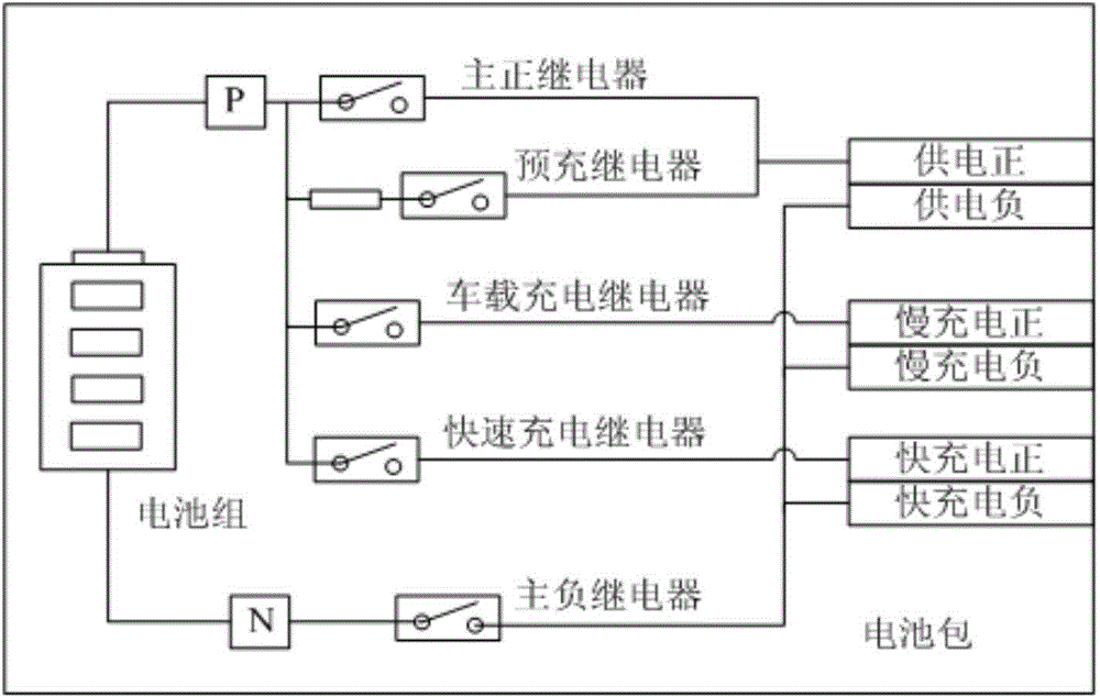
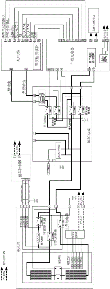
[0039] refer to figure 2, the electric vehicle charging system in the present invention mainly includes a battery pack, a vehicle controller, a DCDC assembly, and an on-board charger. figure 2 is also shown in .

[0040] Inside the battery pack are mainly battery cells, high-voltage relays, pre-charging resistors, battery m...


PUM


Abstract

The invention provides an electromobile charging system which comprises a battery pack, a main positive relay, a main negative relay, an electromobile controller, a quick-charging relay, a quick-charging auxiliary relay, a slow-charging relay, a slow-charging auxiliary relay and an electromobile-mounted charger. Normally-open contacts of the quick-charging relay and the slow-charging relay are in series connection, and normally-open contacts of the quick-charging auxiliary relay and the slow-charging auxiliary relay are in series connection. The invention further provides a control method adopting the electromobile charging system for quick charging and slow charging. By the electromobile charging system and the charging control method, charging safety of an electromobile can be improved.

Description

technical field [0001] The invention relates to the field of electric vehicles, in particular to an electric vehicle charging system and a charging control method. Background technique [0002] In the case of increasingly serious environmental pollution and depletion of fuel resources, electric vehicles have become a key development direction. Generally, electric vehicles provide two charging modes: fast charging mode and slow charging mode (also called on-board charging mode). In the slow charging mode, the on-board charger arranged in the car is powered by the mains power supply or the slow charging interface of the charging pile, and the on-board charger converts the alternating current into the slow charging voltage required by the battery pack (also called the power battery pack). ; In the fast charging mode, the fast charger inside the charging pile outputs direct current to charge the battery pack directly. [0003] Electric vehicle charging systems in the prior art...

Claims


Application Information

Patent Timeline
Patent Type & Authority Applications(China)
IPC IPC(8): H02J7/00B60L11/18
CPCB60L53/60H02J7/0072Y02T10/70Y02T10/7072Y02T90/12
Inventor 丁更新
Owner ANHUI JIANGHUAI AUTOMOBILE GRP CORP LTD
Why Eureka
Try Eureka