Vertical finish-milling machine

A precision milling machine, vertical technology, applied in milling machines, milling machine equipment, metal processing machinery parts, etc., can solve the problems of small effective distance, small workpiece range, high machining accuracy, etc., to increase the longitudinal working distance, increase machining range, the effect of increasing the machining accuracy

Inactive Publication Date: 2015-05-13
广东习铭模具工业有限公司
View PDF12 Cites 15 Cited by
  • Summary
  • Abstract
  • Description
  • Claims
  • Application Information

AI Technical Summary

Problems solved by technology

[0003] The existing vertical fine milling machine generally includes a gantry column, a beam and a worktable mechanism. The headstock is fixed on the beam guide rail through the carriage. There are guide rails on the board, and the headstock can move up and down along the guide rail of the carriage. The movement of the headstock drives the milling cutter to move. When the box moves suddenly and greatly, it is easy to cause vibration and unbalanced movement of the milling cutter, which makes it difficult to achieve high machining accuracy
Moreover, the general volume of the spindle box and the carriage is limited, and the range of its movement up and down along the carriage is also small, so the working distance of the milling cutter is also small, and the effective distance of its work is also small, which leads to the milling cutter. The working depth is also smaller, and the range of machining workpieces is much smaller
Existing fine milling machine tools, the worktable purchased by the workbench machine is fed in the X direction along the guide rail of the workbench base. The length of the workbench base is generally about 1.5 times the length of the workbench. When the workbench moves to the end , there will be a part suspended in the air, that is, the worktable guide rail half supports the workbench, the load capacity of such a workbench structure is not large enough, and it cannot withstand the processing of some large workpieces, which limits the processing range of the milling machine, and when the workbench part When suspended, the guide rail on the back of the workbench is partially separated from the base guide rail, so that the workbench guide rail is easily scratched by the guide rail of the workbench base, reducing the service life of the workbench, and the workbench with this semi-supporting structure is not stable enough. prone to danger

Method used


Image

  • Vertical finish-milling machine
  • Vertical finish-milling machine
  • Vertical finish-milling machine

Examples


Embodiment Construction

[0029] The present invention is further described in conjunction with the following examples.

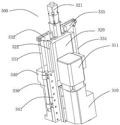
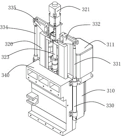
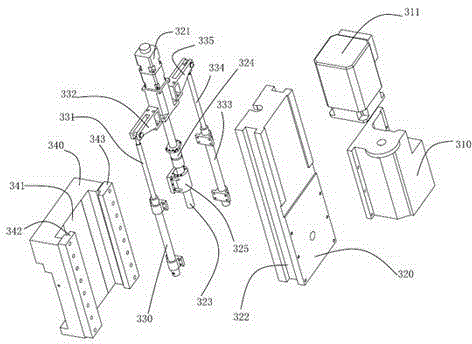
[0030] Such as figure 1 As shown, the vertical fine milling machine of the present invention includes a gantry column 100 , a beam 200 arranged on the gantry column 100 , a headstock mechanism 300 and a worktable mechanism 400 installed on the beam 200 . Among them: such as figure 2 , image 3 , Figure 4 with Figure 5As shown, a spindle box 310, a spindle servo motor 311, a ram 320, a ram motor 321, a pair of balance cylinders (left balance cylinder 330, right balance cylinder 333) and a carriage 340; the spindle box 310 is fixed on the ram 20, the milling cutter of the fixed finish milling machine is installed on the spindle box 310; the spindle servo motor 311 is fixed on the spindle box 310 and provides driving force for the milling cutter; the ram 320 is arranged in a cuboid shape, and the carriage 340 is provided with a receiving groove 341, the ram 20 is arranged in th...


PUM


Abstract

The invention relates to a metal processing machine tool, in particular to a vertical finish-milling machine which comprises a gantry column, a transverse beam, a main shaft box mechanism and a working table mechanism, wherein balance oil cylinders are respectively and symmetrically arranged on two sides of a ram of the main shaft box mechanism; one end of each balance oil cylinder (the shaft end of the oil cylinder) is fixed on the ram; the other ends of the balance oil cylinders (the body ends of the oil cylinders) are fixed on a drag plate. When the ram drives a main shaft box to move upwards and downwards, the situation that a cutter drops off can be avoided no matter what the moving amplitude is; moreover, when a milling cutter moves suddenly, the moving speed of the main shaft box can be effectively buffered by the balance oil cylinders; due to adoption of the balance oil cylinders on two sides of the ram, the ram is relatively stable, the processing precision of the finish-milling machine can be relatively high, and a processed workpiece is relatively good in quality. After the guide tracks of a working table base are lengthened, the working table can be completely supported, and the bearing property of the working table is improved. Three transverse beam guide tracks are provided, so that abrasion of the guide tracks is alleviated, and the service lives of the guide tracks are prolonged.

Description

technical field [0001] The invention relates to a metal processing machine tool, in particular to a vertical fine milling machine. Background technique [0002] A finish milling machine is a machine tool (milling machine) that uses a milling cutter to process various surfaces on a workpiece. On the milling machine, planes (horizontal planes, vertical planes), grooves (key slots, T-slots, dovetail slots, etc.), toothed parts (gears, spline shafts, sprockets), and spiral surfaces (threads, spiral grooves) can be processed on the milling machine. and various surfaces. In addition, it can also be used to process the surface and inner hole of the rotating body and perform cutting work. When the milling machine is working, the workpiece is installed on the worktable or the accessories such as the indexing head. The main movement of the milling cutter is the rotation, supplemented by the feed movement of the worktable or the milling head, and the workpiece can obtain the required...

Claims


Application Information

Patent Timeline
Patent Type & Authority Applications(China)
IPC IPC(8): B23C1/06B23Q1/01B23Q1/25B23Q11/00B23Q1/62B23Q5/40
CPCB23C1/06B23Q1/017B23Q1/25B23Q1/62B23Q5/40B23Q11/00B23Q2701/04
Inventor 向成松
Owner 广东习铭模具工业有限公司
Why Eureka
Try Eureka