
Energy-saving setting machine

A technology of setting machine and waste heat recovery device, applied in heating/cooling fabrics, textiles and papermaking, fabric surface trimming, etc., can solve the problems of increasing power consumption, increasing air volume, heat waste, etc. Guarantee the effect of environmental protection

Inactive Publication Date: 2015-05-13
SHAOXING MINGFENG ENERGY SAVING TECH
View PDF8 Cites 11 Cited by
  • Summary
  • Abstract
  • Description
  • Claims
  • Application Information

AI Technical Summary

Problems solved by technology

The lost heat not only wastes energy but also causes environmental pollution. It is imperative to recover the waste heat of the heat setting machine
[0004] The traditional heat setting machine mainly has the following disadvantages: 1. It is bulky and consumes a lot of auxiliary materials, which is inconvenient to install; 2. The wind resistance is large, which increases the power consumption of the exhaust fan; 3. Forced air supply increases power consumption and air volume. Destroy the hot air circulation in the oven; 4. The air intake and exhaust pipes are long, resulting in large heat loss
5. Due to the long route between the exhaust gas pipe and the exchanger, the temperature is high and the exhaust pipe is easy to catch fire, and the frequency of fires is high
6. Improper waste heat recovery application measures lead to unsatisfactory energy saving and emission reduction effects

Method used


Image

  • Energy-saving setting machine
  • Energy-saving setting machine

Examples


Embodiment Construction

[0014] The following will clearly and completely describe the technical solutions in the embodiments of the present invention with reference to the drawings in the embodiments of the present invention.

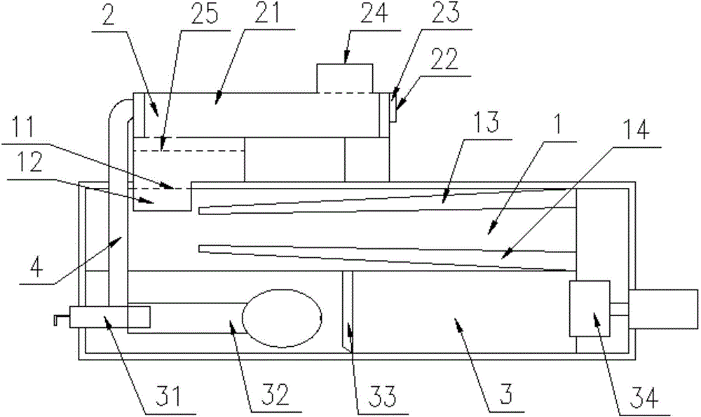
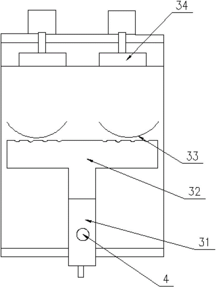
[0015] Such as figure 1 and figure 2 As shown, the energy-saving setting machine includes an oven 1, a heat supply device 3 and a waste heat recovery device 2. The waste heat recovery device 2 includes a heat exchanger 21, and the heat exchanger 21 adopts a differential type exchanger. The patent number is ZL201320416519.9 . The heat exchanger 21 is connected to the waste gas discharge port 24 in the waste heat recovery device 2 and the air supply port 22 provided with the blower 23, and is also connected to the waste discharge port 11 of the oven 1, and is connected to the heat supply device 3 through the waste heat recovery pressure air pipe 4. connection; the waste gas discharge port 24 in the waste heat recovery device 2 communicates with the waste discharge port 11 of ...


PUM


Abstract

The invention discloses an energy-saving setting machine and belongs to the field of textile machines. The energy-saving setting machine comprises a drying oven, a heat supplying device and a waste heat recycling device, wherein the waste heat recycling device comprises a heat exchanger, the heat exchanger is connected with a waste gas discharge outlet in the waste heat recycling device and an air supplying hole with a blower, the heat exchanger is further connected with a waste discharge hole of the drying oven, and also connected with a heat supplying device through a waste heat recovery pressure ventilation pipe, the waste gas discharge outlet of the waste heat recycling device is communicated with the waste discharge hole of the drying oven, the air supplying hole of the waste heat recycling device is communicated with the heat supplying device, the heat supplying device comprises a burner, a heat supplying air pipe, and an internal exchange fan, the burner is connected with the waste heat recycling pressure ventilation pipe and the heat supplying air pipe, the internal exchange fan is arranged at a joint of the heat supplying device and the drying oven, the heat supplying air pipe of the heat supplying device is a 'T'-shaped air pipe, and a 'C'-shaped baffle is also arranged at the front end of the heat supplying air pipe. The energy-saving setting machine has the advantages that the effects of saving energy and protecting the environment are realized, and safety factor is also increased.

Description

technical field [0001] The invention belongs to the field of textile machinery, in particular to an energy-saving setting machine. Background technique [0002] In recent years, with the rapid expansion of the production capacity of printing and dyeing enterprises, the number of new setting machines has increased dramatically, and the environmental complaints and pollution disputes caused by the waste heat discharge of setting machines are increasing day by day. Waste heat recovery of setting machine is a multi-benefit project, which can produce significant economic and social benefits in terms of energy saving and consumption reduction, environmental protection, quality improvement of setting fabrics, and improvement of workshop environment. Heat setting machine is one of the main energy-consuming equipment in the textile dyeing and finishing industry. The heat setting machine is a device that uses hot air to dry, finish and shape the fabric. There are many ways to supply...

Claims


Application Information

Patent Timeline
Patent Type & Authority Applications(China)
IPC IPC(8): D06C7/02
CPCD06C7/02
Inventor 王越丰
Owner SHAOXING MINGFENG ENERGY SAVING TECH
Learn More