Supercharge Your Innovation With Domain-Expert AI Agents!

A high-precision roll angle measurement method and device for optical drift compensation of all optical paths

A technology for roll angle measurement and light measurement, which is applied in the field of optical measurement, can solve problems such as the inability to eliminate the influence of angle drift, limit measurement accuracy, and difficulty in parallel adjustment of double beams, so as to improve measurement resolution, compact optical structure, and facilitate on-site measured effect

Inactive Publication Date: 2017-08-22
ZHENGZHOU UNIVERSITY OF LIGHT INDUSTRY
View PDF7 Cites 0 Cited by
  • Summary
  • Abstract
  • Description
  • Claims
  • Application Information

AI Technical Summary

Problems solved by technology

This type of method has a simple structure and is easy to measure and integrate multiple parameters at the same time, but the parallel adjustment of the two beams is difficult. In addition, the influence of laser beam drift limits the improvement of measurement accuracy.
Although the common-path structure and the dual-optical-path differential method adopted in the method proposed in the Chinese patent ZL2010101664995 and the document "Research on Roll Angle High-Precision Measurement Method in Simultaneous Measurement of Multi-DOF Errors" (Zhai Yusheng, doctoral thesis, Beijing Jiaotong University, 2012) Measurement can basically eliminate the influence of laser beam parallel drift and common mode noise, but the influence of laser beam angle drift on a single optical path in the dual optical path still cannot be eliminated

Method used


Image

  • A high-precision roll angle measurement method and device for optical drift compensation of all optical paths
  • A high-precision roll angle measurement method and device for optical drift compensation of all optical paths
  • A high-precision roll angle measurement method and device for optical drift compensation of all optical paths

Examples


Embodiment Construction

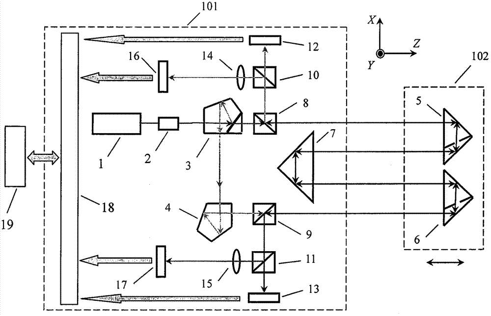
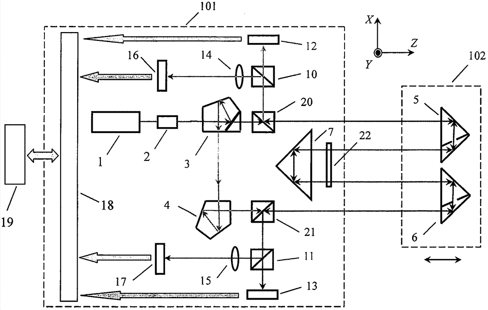
[0027] The present invention will be further described below in conjunction with the drawings.

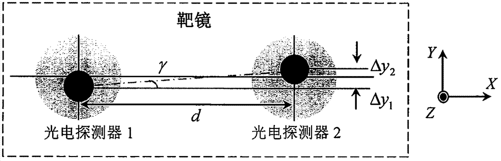
[0028] The roll angle measurement of the present invention is based on the parallel double beam combined measurement method. The measurement principle of the parallel double beam method is as follows figure 1 As shown, two parallel light beams with a distance of d in the x-axis direction are respectively perpendicularly incident on the two photodetectors fixed on the target mirror (moving unit) along the z-axis direction. When the target mirror rolls around the z-axis (parallel to the direction of the collimated beam) with a γ angle, the position of the beam on the photodetector changes accordingly. Suppose the y-axis displacement of the two beams of light on the detector is Δy 1 And Δy 2 , By the geometric relationship, the roll angle can be approximately expressed as

[0029] γ≈(Δy 2 -Δy 1 ) / d (1)

[0030] The measurement principle and optical path structure design adopted by the meas...


PUM


Abstract

The invention discloses a full optical path drift compensation high-precision roll angle measuring method and a device, and belongs to the technical field of photovoltaic testing. By using a pair of retro-reflector as sensitive device, the roll angle information is obtained through the parallel two-beam differential measurement, in which the parallel beam through a set of double pentagonal prism and a pentagonal prism splitting the collimated laser beam after splitting obtained by the dual beam parallelism prism precision guaranteed without adjustment, greatly enhance the feasibility and practicability of measurement methods; by using a rectangular prism as beam translation and reverse means that two beams measuring light path completely overlap, and the light path direction reciprocal use This feature, in twice while improving measurement resolution, combined with a total path of the light drift compensation method, can achieve all-optical laser beam path is completely drift compensation, to resolve the current measuring method using laser collimation of the laser beam cannot completely eliminate the drift angle the impact of the common problems that can achieve the roll angle measurement resolution of better than 0.1 'accuracy of better than 1'; compact optical structure of the present invention, the adjustment is simple, no more freedom crosstalk error, moving parts without cable, easy on-site measurement .

Description

Technical field [0001] The invention belongs to the technical field of optical measurement, and particularly relates to a method and device for measuring a roll angle that realizes complete compensation of laser light drift. Background technique [0002] In the fields of high-precision machinery manufacturing, processing, inspection, etc., it is very important to correct geometric and motion errors to improve the accuracy of linear motion systems. Therefore, the high-precision measurement method and technical research of six-degree-of-freedom error has always been an important topic, and the roll angle error It is the most difficult parameter to measure among the six degrees of freedom error. In addition, the roll angle measurement is also widely used in gesture recognition, installation and positioning. [0003] The traditional roll angle measurement method is mainly based on the electronic level based on the direction of gravity and the combined measurement method based on the p...

Claims


Application Information

Patent Timeline
Patent Type & Authority Patents(China)
IPC IPC(8): G01B11/26
Inventor 翟玉生张志峰薛人中耿利杰杨鹏苏玉玲王新杰
Owner ZHENGZHOU UNIVERSITY OF LIGHT INDUSTRY
Features
  • R&D
  • Intellectual Property
  • Life Sciences
  • Materials
  • Tech Scout
  • Unparalleled Data Quality
  • Higher Quality Content
  • 60% Fewer Hallucinations
Learn More