A correlative optical time domain reflectometer based on an all-fiber wide-spectrum chaotic light source

An optical time domain reflectometer and optical time domain reflectometry technology, applied in electromagnetic wave transmission systems, electrical components, transmission systems, etc., can solve the problem of impossible long-distance sensing, signal power and detector gain limitations, and technical difficulties Large and other problems, to achieve the effect of simple structure, low cost, high-precision spatial resolution

Active Publication Date: 2017-08-11
UNIV OF ELECTRONICS SCI & TECH OF CHINA
View PDF11 Cites 0 Cited by
  • Summary
  • Abstract
  • Description
  • Claims
  • Application Information

AI Technical Summary

Problems solved by technology

However, optical frequency domain reflectometry requires fine frequency-sweeping light sources and homodyne coherent detection, and its technical difficulty is greater than that of optical time domain reflectometry, and low-coherence frequency domain reflectometry is basically impossible for long-distance sensing
The prior technology CN101226100A uses LD-pumped chaotic light source to achieve 6cm sensing accuracy, but limited by its signal power and detector gain, its sensing distance is only tens of meters

Method used


Image

  • A correlative optical time domain reflectometer based on an all-fiber wide-spectrum chaotic light source
  • A correlative optical time domain reflectometer based on an all-fiber wide-spectrum chaotic light source
  • A correlative optical time domain reflectometer based on an all-fiber wide-spectrum chaotic light source

Examples


Embodiment Construction

[0022] The present invention will be described in detail below in conjunction with the accompanying drawings.

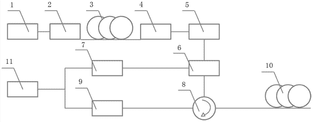
[0023] Such as figure 1 Shown is a schematic structural diagram of a correlated optical time domain reflectometer based on an all-fiber broadband chaotic light source according to the present invention. The system includes a 1455nm Raman pump light source 1, an optical isolator 2, and zero dispersion shifted optical fibers 3, 1, 2, 3 form an all-fiber ultra-broadband chaotic light source; the system also includes an adjustable optical attenuator 4, an optical filter 5, a coupler 6, photodetectors 7 and 9, and a circulator 8; the test fiber (G.652) 10 and real-time oscilloscope11. The length of the zero-dispersion-shifted optical fiber 3 is 16 km, and its length determines the pump power required by the ultra-broadband chaotic light source. In the present invention, the length of the zero-dispersion-shifted optical fiber 3 should be between 10-20 km. The center wave...


PUM


Abstract

The invention discloses a correlated optical time domain reflectometer based on an all-fiber wide-spectrum chaotic light source, and relates to the fields of chaotic fiber lasers and optical time domain reflectometers. The reflectometer includes: all-fiber chaotic light source and related optical time-domain reflectometry system; related optical time-domain reflectometry system includes: adjustable attenuator, optical filter, coupler, circulator, photodetector, oscilloscope; all-fiber The output light of the chaotic light source is injected into the correlation type optical time domain reflection system, and first passes through the adjustable attenuator, the optical filter, and the coupler in turn, and the chaotic optical signal passing through the coupler is divided into a reference signal and a detection signal, and the reference signal is directly obtained by the The photoelectric detector is converted into an electrical signal and collected and stored by an oscilloscope; the detection signal passes through a circulator to realize the function of a reflector, and the reflected signal is converted into an electrical signal by another photodetector and then collected and stored by the same oscilloscope. The invention has the advantages of simple system structure, high stability, high resolution sensing and long distance at the same time.

Description

technical field [0001] The invention relates to the fields of chaotic fiber lasers and optical time domain reflectometers, in particular to a correlation type optical time domain reflectometer based on full fiber broadband chaotic lasers. Background technique [0002] With the development of the information society, optical fiber communication and sensor networks are becoming larger and larger, and they are playing an increasingly important role in people's lives. For optical networks and devices, optical reflectometer technology is an important means of fault diagnosis. In this context, the development of optical reflectometer technology has received more and more attention. [0003] Optical reflectometer technology mainly includes three types: optical time domain reflectometry, low coherent frequency domain reflectometry, and coherent optical frequency domain reflectometry. These three optical reflectometer technologies are restricted in various indicators such as measure...

Claims


Application Information

Patent Timeline
Patent Type & Authority Patents(China)
IPC IPC(8): H04B10/071
Inventor 王子南范孟秋饶云江
Owner UNIV OF ELECTRONICS SCI & TECH OF CHINA
Why Eureka
Try Eureka